
Archives for Knowledge centre

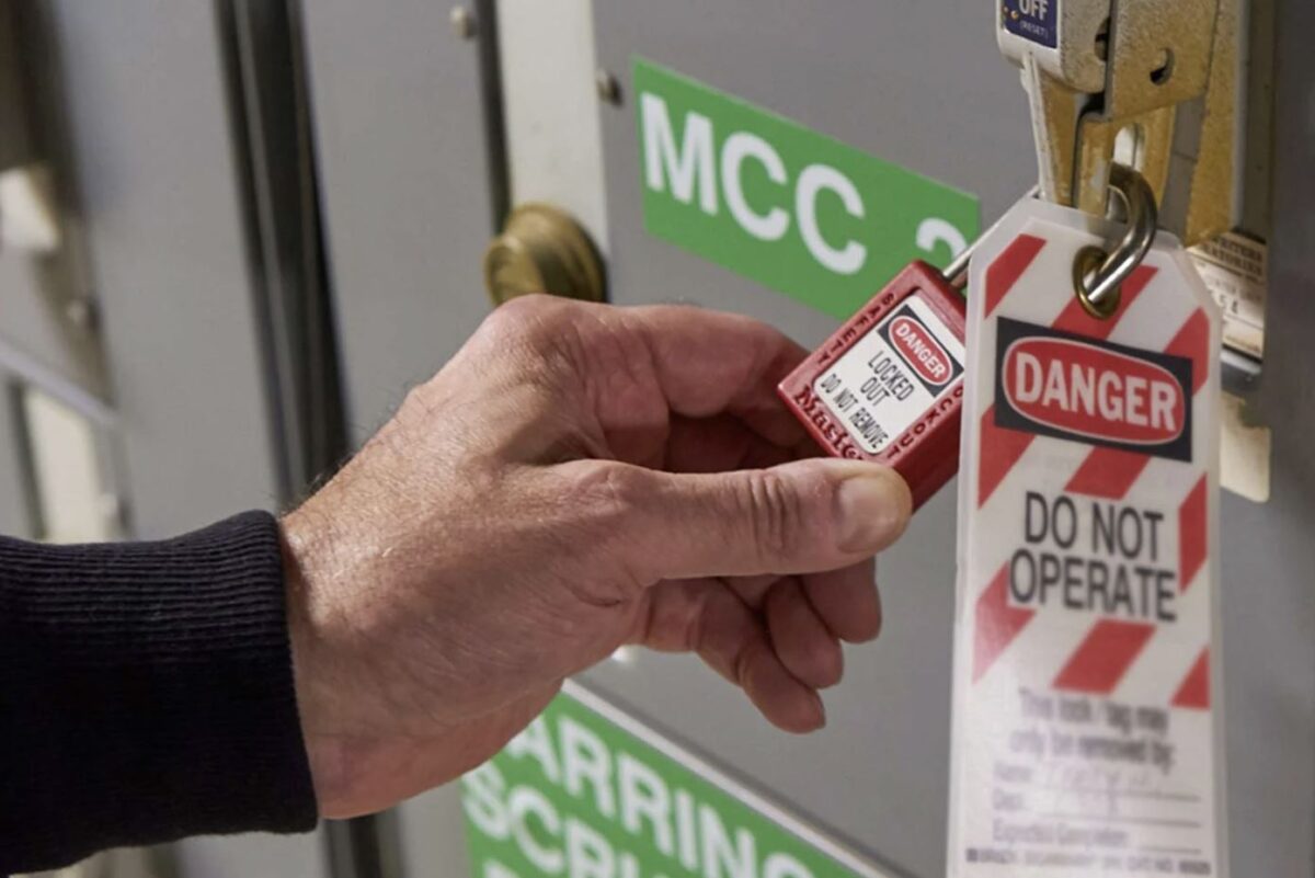
Building a strong culture of safety

3 key principles for building a strong culture of safety

According to a survey by Fluke most companies do not have a strong safety culture. To build a strong culture of safety, you must first create a climate of safety. A climate of safety allows for faster change and adaptation. It influences safety culture, which is harder to change because it is intertwined with the overarching corporate culture. If you want to change a company's safety culture, you have to start with the climate of safety. Over time, that strong climate will create a stronger culture.

The safety culture expert at Predictive solutions, Chuck Pettinger, Ph.D. has seen three key changes in creating a successful climate of safety that will evolve into a successful culture of safety:

  1. Communications
  2. Make it personal
  3. Keep building

1. Communicate

Part of a successful business is how we communicate with each other and building a strong culture of safety. Looking at a climate of safety communication can include things like goal setting and incentive programmes. Instead of looking at accident and injury rates, Dr Pettinger suggests focusing on the positive. By focusing on accidents and injuries, “a lot of safety reporting goes underground. And it can unintentionally damage the culture.” Instead, try focusing on the quality of safety inspections or the number of employees participating in a safety initiative. In general, people are more motivated when they try to improve something, rather than avoid or reduce something (e.g. injuries).

Instead, focus on setting S.M.A.R.T. goals, which are more useful and have a positive impact on the climate of safety within the company. Dr Pettinger says: “[The goal] should be an actionable, observable behaviour that you want to reinforce, versus, for example, ‘Do your best.’ So make it specific. Make it achievable. Make it relevant to the people around you and not just you. And visualise it, make people see its importance.”

It is also important to be aware of how you talk about certain processes. This can also affect how the climate is perceived throughout the company. Dr Pettinger gave an example of how climate can affect employees negatively: “If you hear, ‘We need to get this machine running.’ There is a certain time pressure. There is a slight pressure and nobody is literally telling you ‘Skip things’, but you feel that pressure of climate compared to other cultures that say, “I don't care how long it takes. Take your time. Do it safely. Don't get hurt.”

2. Make it personal

Creating a safety plan that focuses on the individual will keep you engaged with it throughout the working day. Dr Pettinger has seen success in changing the way meetings are held at the beginning of the shift and making training more customised.

More employee engagement at the beginning of the shift has had a positive effect for many companies. Instead of just looking at what needs to be done and what the previous shift left out, Dr Pettinger recommends taking time during each meeting to discuss potential risks and how they can be mitigated. “Make sure you get those answers from the people in your group. As a good manager, it is important to let them find the solution themselves,” says Dr Pettinger.

When it comes to training and teaching, different approaches are possible. Michael Brooks, a Fluke customer, has had success with one-to-one training at his company, Great Southwestern Fire and Safety. Taking the time to go through the safety steps and ensuring that the knowledge and experience one employee has is transferred to the next. Brooks said, “What they learnt, they themselves could transfer to another new colleague. It's not the same people instructing and learning and growing all the time. We have really worked hard to maintain this positive attitude among our staff.” This has not only contributed to employee safety, but has allowed the company to grow over the years.

3. Keep building

Building a strong culture of safety does not happen overnight. Many companies fall under the so-called ‘toxic cycle’. In this cycle, new initiatives start strong, but eventually lose momentum and are completely ignored after some time. Then another new initiative is started and the cycle repeats itself. However, no real change is seen based on these initiatives and both the climate and culture of safety remain the same.

Instead, companies must find a way to achieve the “virtuous cycle”. This is all about patience and perseverance. “Culture is something that is very difficult to influence. It sometimes takes three to five or even 10 years to change,” Dr Pettinger said.

Once a new initiative has started, set short-term goals to make it feel more like progress is being made. Not only will individual employees feel they can be more influential, but management can also keep track of what changes have been initiated. Once people see the value of the new process, it will become self-perpetuating, ingrained and help your organisation create a culture of safety.

Read more
myths about electricity

Four myths about electricity that may surprise you

Several myths about electricity are ubiquitous. Plant safety is much more than just some tasks on a checklist. It requires commitment from every employee, from management to line workers, to maintain a culture of safety in all aspects of operations. Over time, interpretations of certain safety standards may differ from the original intent, creating myths about how best to meet safety requirements.

Ask our experts for advice


Myth 1: “Awkward” is the same as “unfeasible” when it comes to de-energising equipment for maintenance

Debunk four surprising myths about electricity and strengthen your knowledge. Informative insights now on LHM-instrumentation.co.uk.

Of course, it is almost never convenient when the power has to be turned off unexpectedly to work on a piece of equipment. But that does not mean it is not feasible. The European Agency for Safety and Health at Work (EU-OSHA), national equivalents such as the Health and Safety Executive (HSE) in the UK and the DGUV (German statutory accident insurance), as well as other local authorities, only allow working on a live circuit under certain circumstances. This includes when it is ‘unfeasible’ to switch off the power because of increased risk. However, there is a tendency to allow workers to work on live circuits just because it is “inconvenient” to switch off the power. This leads to unnecessary risks that often lead to accidents.

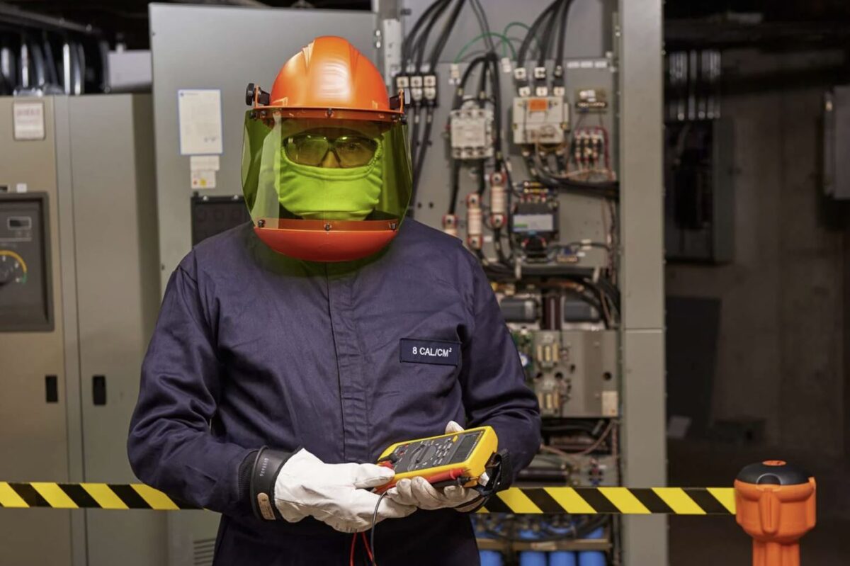
In situations where it is impossible to switch off the power, only electricians and technicians qualified to work on live systems should carry out the work. They should take all precautionary measures, including wearing the appropriate personal protective equipment (PPE) and using tools certified according to the applicable safety standards (e.g. EN 60900) for the relevant conditions.

Myth 2: The more personal protective equipment, the better

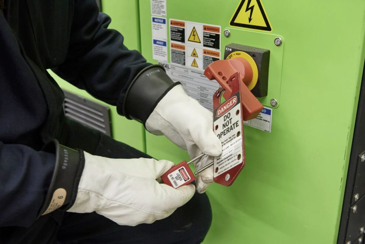
Debunk four surprising myths about electricity and strengthen your knowledge. Informative insights now on LHM-instrumentation.co.uk.Whether to wear personal protective equipment, and how much, is not a matter of personal choice. A component can fail at any time. Perfectly working circuit breakers can suddenly malfunction while troubleshooting. If an arc occurs just by opening a cabinet, wearing the right personal protective equipment can mean the difference between life and death. Electricians and technicians should follow the detailed personal protective equipment requirements in European standard EN 50110 “Operation of electrical installations”, which defines electrical safety in the workplace. However, requiring workers to wear personal protective equipment classified for a much higher risk level than required by the environment does not necessarily make them better protected.
“More personal protective equipment is not necessarily better,” says Kevin Taulbee, Electrical Engineer and Safety Trainer at Power Studies, Inc. “It's all about using the right personal protective equipment. Doing a proper hazard analysis before the job is important to equip employees with the right PPE. Too many people just buy arc-resistant moon suits and thick high-voltage gloves for cable workers for their in-house maintenance workers and electricians. Class 2 electrical gloves are not necessary if they never come into contact with a voltage of more than 480 V, and they offer much less freedom of movement. As a result, an electrician is more likely to drop tools or test leads when working on a live panel.”

In addition to choosing the right PPE, it is possible to choose hand tools designed to make it easier to operate buttons and dials when heavy gloves are worn. It is also possible to reduce the number of personal protective equipment required in some cases by equipping workers with non-contact infrared instruments (IR instruments), such as thermal imaging cameras, infrared thermometers and wireless monitoring sensors. These tools allow workers to capture data from outside the arc zone. Removing the need to work within an arc boundary, especially when switching or troubleshooting, increases the overall level of safety for workers.

Myth 3: All test leads and fuses are the same

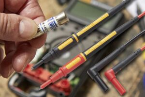
myths about electricityOften technicians consider test leads and fuses as basic components without paying much attention to quality. Regardless of the quality of the multimeter, it is only as safe as the test leads used and the fuses inside. These components provide essential protection against current and voltage spikes that can cause serious injury to the user.
Choosing the right test leads

The main task of test leads is to connect the digital multimeter to the device to be tested, but they are also a first line of defence against electrocution. Measurement leads that are poorly made, worn out or not suitable for the work to be performed can produce inaccurate readings and pose a serious shock hazard if touched with the wrong wire. When choosing measurement leads, pay attention to the following:

  • High-quality materials and robust construction
  • Classification for the relevant measurement category as specified in EN 61010 and the voltage level of the application. The category (CAT) of the measuring leads and accessories must match or exceed the category of the DMM.
  • Exposed metal corresponding to the energy potential of a specific measurement.
  • Retractable measuring pins, measuring pin sleeves or measuring pins with shorter ends to prevent accidental short circuits.

Choose high-quality replacement fuses

Current safety standards require that digital multimeters are equipped with special high-power fuses designed to keep the energy generated by an electrical short circuit within the fuse housing. This protects the user from electric shock and burns. When it is time to replace fuses, always choose high-power fuses approved by the meter manufacturer. Cheaper generic replacement fuses increase the risk of serious injury.

Myth 4: The only way to accurately measure voltage is to make contact with a test lead.

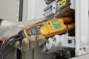
Fluke T5 testersIn the past, connecting test lead probes or crocodile clips directly to electrical conductors was the best way to obtain accurate results. However, this requires metal-to-metal contact, which increases the risk of arcing and possible injury to the person measuring or damage to the equipment being measured.
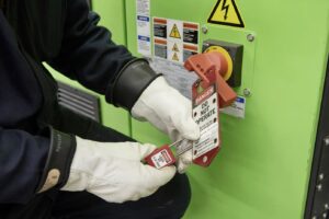
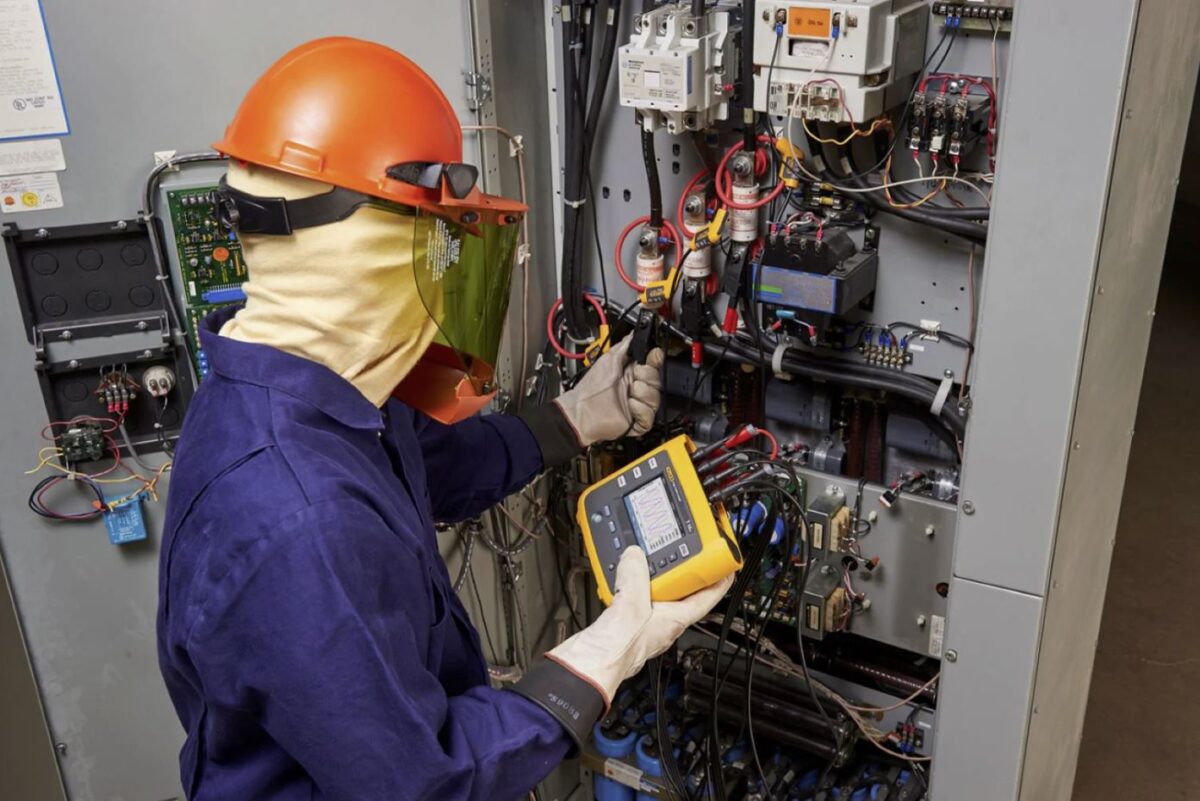
Recently, a novel technology introduced that detects and measures voltage without metal-to-metal contact. This technology isolates the measuring instrument from the voltage source under test. To measure voltage, electricians and technicians slide only one conductive wire into the open fork of the hand-held measuring instrument. Because they are not exposed to live contact points, there is less risk of electric shock and arcing.

The myths mentioned above are just a small selection of the safety issues that should be considered when working on live equipment. The best way for a facility to ensure that employees fully understand and comply with all relevant electrical safety regulations is to develop and maintain a solid safety culture based on the needs and environment of that particular facility.

Read more
working with electricity, 10 silly things

Ten stupid things smart people do

Anyone who makes a living working with electricity soon develops a healthy respect for anything that could be even remotely live. Yet time constraints and stress due to the critical nature of the equipment can lead to carelessness and uncharacteristic mistakes even in the most experienced electrician. The list below provides a quick overview of what not to do when measuring electricity.


Ask our experts for advice

  1. Replacing the original fuse with a cheaper one. If your digital multimeter meets current safety standards, that fuse is a special sand-filled fuse that will burn out before an overload can reach your hand. If you change the fuse on your DMM swapped, always replace it with a fuse approved for the instrument.
  2. Use a piece of wire or metal to bridge the complete fuse. This may seem like a quick fix for when you unexpectedly do not have a spare fuse with you, but that fuse is the only thing separating you from the voltage spike coming your way.
  3. Using the wrong tool for the specific job. It is important that your DMM is suitable for the work you will be performing. Always ensure that your measuring instrument has the correct safety specification for the work you are doing, even if this means changing DMMs throughout the day.
  4. The cheapest DMM choose. You can always switch to a more expensive model later, right? Maybe not, either, if you become the victim of an accident. This is because the cheap measuring instrument did not have the safety features indicated. Always look for statements from independent testing laboratories.
  5. Leaving your safety glasses in your breast pocket. Get those glasses. Put them on. It's really important. The same goes for insulating gloves and flame-resistant clothing.
  6. Working on a live circuit. If at all possible, de-energise the circuit. If you do have to work on a live circuit, use properly insulating instruments, wear safety goggles or face shield; and insulating gloves, remove watches and jewellery, stand on an insulating mat and wear flame-resistant clothing instead of ordinary work clothes.
  7. Failure to provide proper safeguards and texts against reactivation of the installation.
  8. Use both hands when measuring. Do not do this! When working on live circuits, use the following trick: Keep one hand in your pocket. This reduces the risk of a closed circuit through your chest and heart. Hang the measuring instrument if possible, or place it somewhere. Touch the instrument with your hands as little as possible to minimise exposure to the effects of transients.
  9. Neglecting your test leads. Measurement leads are important for the safety of the DMM. Make sure your measurement leads also have the right safety specification for the work you are doing. Preferably use measurement leads with double insulation, insulated input connectors, finger protection and non-slip surface.
  10. Keep using your old measuring instrument. Today's measuring instruments have safety features no one had heard of a few years ago; features that are worth modernising your equipment and are a lot cheaper than a visit to the emergency room.
Read more

Rendering cost savings for industrial energy efficiency

energy savingWhat does measurement have to do with energy saving? It's all about efficiency and the end result.

Industrial facilities need to consume energy to stay in operation, produce or generate data, whatever it is, and most facilities waste too much electricity in the process. They are inefficient users of energy. Twenty years ago, facility managers did not worry about energy efficiency - energy was cheap. As energy became more expensive, managers became increasingly interested in reducing their energy bills, but the measures had to be translated into business terms.

Where is the tipping point where waste is so great that it makes sense to address it?

To answer this question, you need to measure how much energy you consume for the different types of labour (systems) in your building and compare it with the standards. This will give you a good overview of how much wastage is taking place. By taking multiple measurements, you can determine what the root cause of the wastage is. The three points of an efficiency comparison are: 1) the amount of wastage combined with 2) the cause and 3) the cost to address it.

Ask our experts for advice

When does saving energy make sense?

Energy conservation makes sense for facilities that want to reduce overheads to increase productivity - facilities that want to do more with less, not just spend less.

Inspection of energy use helps identify opportunities to increase efficiency and gives the facility manager the tools to understand which energy-saving activities make sense, given the facility's primary objectives, and which energy savings do not yield enough return or are too far out of priorities. The greatest opportunities are usually found in facilities with old, large, energy-consuming systems that have not been optimised. Other good candidates are production facilities where not much automation or controls have been implemented, as well as facilities with large steam or compressed air systems.

How much can be saved?

According to the US Department of Commerce (DOE), facilities can reduce their energy bills by up to 25%, but how much can actually be saved depends on a number of things. First, it is necessary to look at what systems are in place and what activities take place in the facility. In particular, large loads that have never been mapped to the utility's tariff schedule, in order to take advantage of the cheapest dayparts, may well yield significant savings. A facility that processes mainly small taxes may not be able to benefit from this option. Secondly, it is necessary to assess how inefficient the building's systems are. A newer, well-maintained facility will not offer as many savings opportunities as an older facility, where systems and equipment no longer meet recommended settings and maintenance procedures.

When you think of energy waste at home, you probably think of draughts penetrating through gaps or old light bulbs being replaced by LEDs. But what kind of “energy waste” occurs in a mixed-use factory or facility?

Using energy to heat or cool air and forcing the ventilation system, which then leaks out of the window, forces the system to overproduce and thus overconsume. How many other systems in the facility work harder than they should because of clogged filters, oversized motors and so on?

So yes, waste can certainly occur in a factory or mixed-use facility, both in terms of lighting and the building envelope. But are these the first types of waste to be addressed?

You can only answer that question if you record energy consumption at all major loads, link it to both the tariff schedule and the operating schedule, and calculate efficiency. Often, so much can be saved in a facility on maintenance and operating processes for major equipment that enough money is saved within a few years to accelerate the replacement of this equipment with a less wasteful model.

Reducing energy consumption when budgets, time and resources are limited

Work from a baseline.

The starting point is to identify where and when energy is used and by what. Once the facility's owners, managers and technicians know exactly how much energy is needed to run the business, relative to the amount of energy being wasted, they can make decisions and determine a strategy. To achieve this status, it is advisable to check the latest utility bills and look for any penalties and charges related to demand during peak hours. Download a copy of the tariff schedule from the utility's website so that you know what energy units cost at different times of the day, compared to your operating schedule. If necessary, contact the utility company directly; they will be happy to help you.

Then instruct your own electricity team or an electrical engineer to log power at main utility entrances and at feeders to the largest systems and loads. Record kW, kWh and power factor over a representative time period. This gives you a very accurate picture of actual energy consumption at three-phase circuits and loads. The biggest savings are often made by shifting load processes to dayparts with cheaper energy costs.

Which systems cause the biggest energy waste?

Assess not only the electrical supply system, but also look at your electromechanical, steam and compressed air systems. These systems are usually full of energy waste, which is nevertheless easy to solve.

Electromechanical
There are five common types of energy waste in an electromechanical system: 1) electrical, 2) mechanical/friction, 3) scheduling, 4) control and 5) sizing/efficiency.
industrial energy savings
A Fluke 1738 use advanced Power Energy Logger to investigate the energy consumption of a mechanical system

  1. Voltage/current overload and unbalanced phasing are two of the most common energy wasters in electromechanical systems. Both electrical problems can be detected with Power Quality Analyzers and thermal imaging cameras.
  2. Energy waste in mechanical systems manifests itself as overheating, as well as excessive vibrations. These can be detected with thermal imaging and vibration meters. Possible causes range from cooling and airflow to bearing alignment and other causes of friction. So perform a thermal scan on couplings, shafts, belts, bearings, fans, electrical components, termination/connection box and windings - all options that may be operating inefficiently and thus wasting energy.
  3. As mentioned earlier, one of the simplest solutions for saving energy is to log energy consumption at large electromechanical loads during a full operating schedule. Determine when equipment consumes the most energy (often at start-up) and check whether usage times can be shifted to dayparts when consumption rates are cheapest.
  4. Using the same consumption log, compare the operating schedule with the frequency at which the appliance consumes energy. How much energy does the appliance consume when not in operation? Without automatic switches, most appliances have to be switched off manually to stop energy consumption, and manual operations are often not performed. Not all appliances can be switched off, but most appliances can be put on standby. Operation can vary, from simple to fully automated; and from operation using sensors and timers to flexibly inactive machines and capturing business processes in a PLC.
  5. Scaling and efficiency levels. Especially in older facilities, it is common for business processes to change but loads to remain unchanged. This means that a large, expensive, start-up motor sometimes drives a system that does not need that much power at all. Branch managers are naturally inclined to use large equipment for as long as possible. However, it is worth looking at how much power the motor uses, compared to the actual load requirements and compared to a new, highly efficient unit of the right size. Calculate how much excess power is consumed and multiply that value by the rate payable. Also determine how long it will take for a new motor to pay for itself: sometimes it makes sense to replace equipment before it breaks down. If not, consider whether you can set the controls to regulate output.

Steam
Process heating accounts for a significant proportion of controllable operating costs and the system should be inspected regularly to avoid various energy waste scenarios.

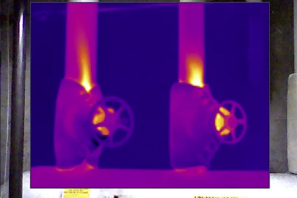
To start with, record energy consumption at the boiler to establish a baseline for energy consumption. Next, inspect the distribution system, including steam traps, manometers, insulation, pumps and valves. Use a thermal imaging camera to detect faulty steam traps, leaks, blockages, value problems and condensate failures: the aim is to return as much pre-heated condensate as possible to the boiler.

You can also use a thermal imaging camera to check for steam leaks. Check for loose or missing insulation and the proper functioning of all steam traps; clean the inside of boilers and check steam transport pipes for blockages. By performing all these actions, you can detect energy waste and help your team plan energy-saving solutions. Many of these can often already be implemented through maintenance, rather than capital expenditure.

Compressed air
A 100-hp air compressor can consume about $50,000 in electricity annually, and 30% of that electricity goes to pressurising air that is never used due to distribution leaks and waste during operation. However, many facilities have never assessed the efficiency of their compressed air processes. When more air pressure is needed, many facilities will purchase and deploy an additional compressor, not realising that they can get more pressure from their existing system.
energy saving in industry
Compressed Air Challenge studies show that only 17% of compressed air users see efficiency as the goal of compressed air system management, but 71% simply want a consistent, reliable air supply. That philosophy manifests itself during operation: facilities with pneumatic equipment often lack even simple solenoid valves, which drive the compressor continuously. Staff on the shop floor often see compressed air as a free resource, using it to clean the work area and even to cool down.

To identify and quantify the level of waste, you can start by logging energy consumption over a full duty cycle across all air compressors. This will give you an insight into how much energy is needed to produce current air pressure levels. Also, using a pressure calibrator record the psi at the compressor output and compare it with the point of use. This allows you to determine the pressure drop and check that the psi required by the manufacturer for pneumatic equipment use is achieved; do not “just use” too much pressure. By connecting a pressure module to a logging multimeter to perform these tests, you don't need to invest in specialised equipment right away. Finally, you can still use a sonic Industrial Imager to scan as much of the air pipe surface as possible to determine the location and extent of air leaks. Find out how great the returns are with these air leakage calculator.

Conclusion

Ultimately, you can make great strides to improve energy efficiency at plant level with these simple and logical best practices. Individually, they already add value, but in combination they can be a treasure trove of energy savings.

Read more
air leak detection equipment

How air leak detection equipment prevents downtime

Fluke interviewed a manufacturer about air leaks. This manufacturer literally keeps the wheels of the industry turning. As one of the world's leading aftermarket manufacturers of wheel service equipment, the company designs, builds and sells products for trusted and leading brands.

Many of this manufacturer's processes depend on compressed air, and the 14,000 sq m factory has some 400 tools, all powered by a 200 hp compressor. “Everywhere in the plant we use compressed air - for pneumatic drives, robotic welders, laser cutting machines and powder coating equipment,” says the plant director. Compressed air usually involves noise, as well as air leaks.

Ask our experts for advice

Reducing energy waste

Air leaks cause compressed air-powered equipment to have to work harder, leading to energy wastage. The likelihood of air leaks in the factory is further increased by the presence of older equipment accumulated over the last few decades due to consolidation of several factories. In such a noisy environment, any leaks are difficult to hear, so most leak detections are carried out outside factory hours.

“We usually wait until it is very quiet in the building, outside working hours or during a maintenance shutdown, and try to detect air leaks by listening as closely as possible,” says the maintenance manager. “We also use bottles of soapy water to spray on an area where we think there is a leak and then see if air bubbles form.” This spray-and-see method requires members of the maintenance team to be close enough to the potential leak to hear it and then spray the soap solution on the right area.

The other method used to detect compressed air leaks is detection with ultrasonic air leak detection equipment. This method can only be carried out by a well-trained person and detecting all leaks takes quite some time. Small leaks can be very difficult to hear with the human ear and not all leaks are in easily accessible places. So detection can be a difficult task.

Make visible what you cannot hear

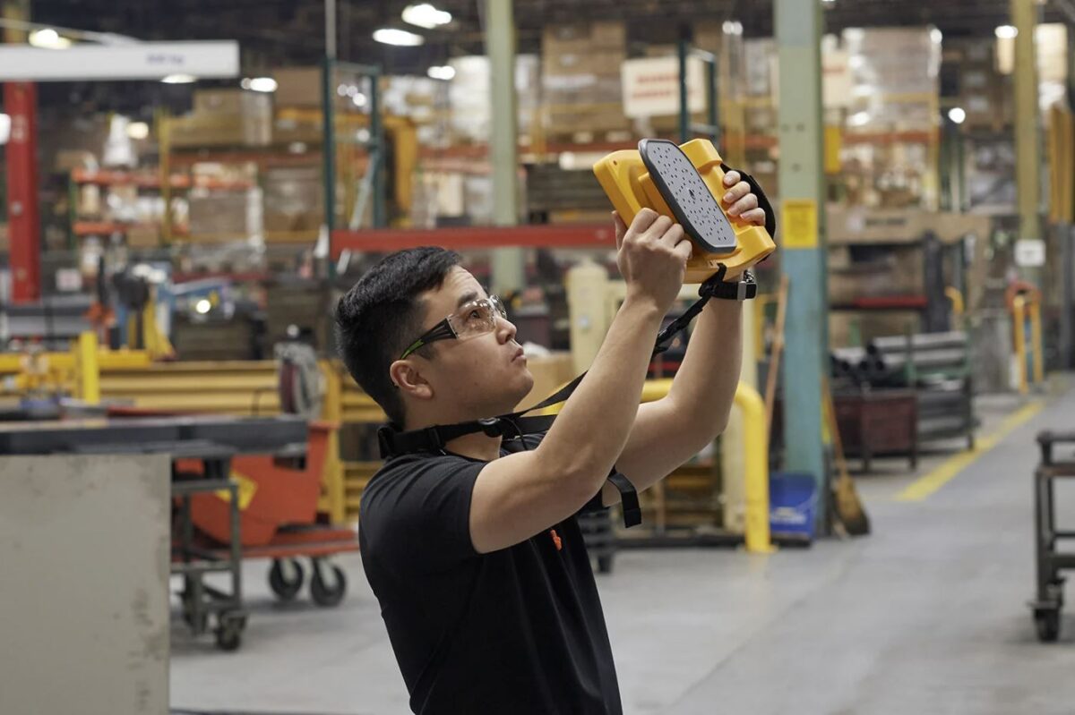
When Fluke approached this manufacturer about whether it would cooperate in testing the Fluke ii900 Sonic Industrial Imager, which can detect leaks up to 50 metres away in a noisy environment, this one was rather sceptical but very willing to try it.

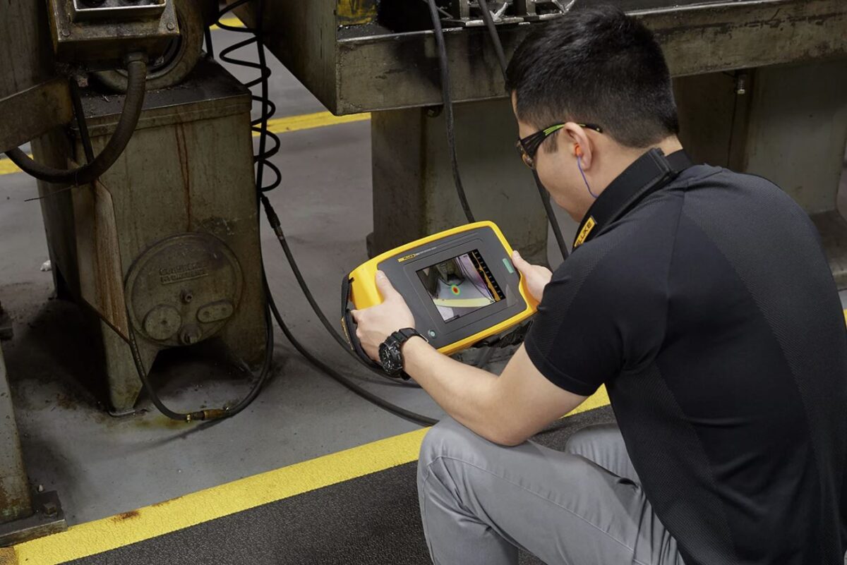
The testing involved both the head of maintenance and the maintenance engineer, who alternately examined the entire plant for leaks for eight hours with two ii900 Sonic Industrial Imagers. The ii900 allowed them to ‘see’ sound while checking hoses, fittings and connections for leaks. The leak survey had a surprising outcome for the production team.

Within one working day, they found around 143 leaks, both large and small.

“I did have some doubts about the leaks the tool found, so I sprayed those spots with soapy water and indeed saw that there was a leak where the tool indicated there was one,” says the maintenance engineer.

The maintenance manager was particularly impressed by the ii900“s ability to find even the smallest leaks. ”Small leaks are very difficult to find,“ he says. ”I noticed there were leaks that the ii900 detected that we would never have found by spraying soapy water on them. We found one leak in an air pipe in the paint room that we could not feel by holding our hand above it or by listening, but it was clear that this leak had been there for some time."

The ii900's built-in acoustic array of sensitive microphones generates a spectrum of decibel levels for each frequency. Based on this output, an algorithm calculates a sound image called a SoundMap™ and this is projected onto a visible image. The SoundMap is automatically adjusted to the selected frequency level to filter out background noise. The SoundMap is updated 10 to 20 times per second on the screen.

Long-range air leak detection

The team quickly detected a leak at 26 feet in an upper air line.

“I was amazed at how easy it was to pick up the Fluke sound imaging camera and walk through the aisles to scan spaces overhead and still detect leaks very quickly,” says the maintenance manager.

The production team recognises that not only are very hard-to-detect leaks now easy to detect, but the ii900 can save significant time and costs. “Once we have found and fixed most of the leaks the first time, we can probably do a follow-up and scan the whole plant in one shift of about eight hours.” That way, huge savings can be made on overtime costs because they can already scan for air leaks during the normal day shift, instead of outside working hours.

It also leads to less energy wastage and wear and tear on equipment. “Air leaks also cause the company to lose a lot of money,” says the maintenance manager. “They are very hard to detect, so it is also difficult to send the maintenance team to the right place. Now we can take a picture of the leak with the Fluke sound imaging camera and send it to our maintenance teams as part of the work order, and it is much more cost-effective. We think it will save us a significant sum of money, both on labour and energy costs.”

Read more
detection of air leaks

Faster detection of air leaks

Even the smallest air leaks can lead to wasted products and energy and loss of production time, especially in a production line that can only function with compressed air to drive tools and processes. Detection of air leaks saves you a lot of money!

If there is not enough compressed air pressure to keep the equipment functioning optimally, there can be costly consequences. The more leaks there are in the system, the harder the compressor has to work to supply the required air to the equipment, which is not optimal for the compressor. This increase in demand increases the risk of insufficient compressed air being supplied to tools and process equipment.

Compressed air leaks also increase energy costs. According to the U.S. Department of Energy, a 1/8″ (3 mm) leak in a compressed air line can cost more than $2,500 a year.


Ask our experts for advice

A partner in air leak detection

How do you make sure you are not behind the curve in controlling air leaks when you have so many other priorities? That is the question a leading heavy equipment manufacturer recently saw answered when it discovered a new partner in the field of air leak detection.

This manufacturer uses between 3058 and 4417 m3/h of compressed air daily. That volume of compressed air serves up to 200 instant tools per line, as well as the process equipment responsible for moving large sheets of steel half an inch thick and positioning parts. Even if there is a leak in one line, it can affect production and increase energy wastage. And that's just one leak...

When Fluke offered the company the chance to develop the new Fluke ii900 Sonic Industrial Imager (Acoustic Imager), they immediately agreed. The ii900‘s array of small, super-sensitive microphones detects sounds in both the range of human hearing and the ultrasonic range and, even more uniquely, allows the user to actually ’see' sound for air leak detection.

“That we can now visualise where the problem is, adds a whole new dimension,” says the company's maintenance manager. “You can identify which thread, coupling or hose the leak is in. It's great to be able to identify on screen exactly where the leak is coming from.”

The ii900 can visually scan large areas up to a distance of 50 metres, speeding up detection of air leaks in the plant and significantly reducing the number of hours previously spent on that task.

“Sometimes we can find and repair as many as 30 to 40 leaks in a few hours,” says the manager. “And we can use the ii900 during production time, when extreme noise is produced, and still find leaks at the roof level 6 to 9 metres away.”

Scanning for leaks without affecting production offers a big advantage for the manufacturer. “Before, it didn't occur to us to test for air leaks during production because we couldn't cordon off the aisles and get people out of a certain area to go up and look at a possible leak,” says the manager. “Now we can stand along the sidelines and scan the air ducts above us while carts and people move underneath. We don't affect their operations and it's better for everyone.”

Read more
detecting gas and vacuum leaks

This is how you detect compressed air, gas and vacuum leaks AND find hidden profits

For industrial plants, compressed air, gas and vacuum systems are an essential source of converted energy. Compressors are simpler than other sources of energy such as electricity and they are everywhere in today's factories. They power machines, tools, robots, lasers, product handling systems and much more.

Yet many compressed air, gas and vacuum systems suffer from wear and poor maintenance, contributing to the biggest waste of all: ever-present leaks. These leaks may be hidden behind machinery or located at connection points, in fixed overhead lines or in cracked pipes or worn hoses. The waste increases rapidly and can even lead to downtime.

Ask our experts for advice


The high cost of wasted air

According to the U.S. Department of Energy, the US Department of Energy, a 1/8″ (3 mm) leak in a compressed air line can cost more than $2,500 a year. The Department of Energy estimates that an average US plant that is not properly maintained can waste 20% of its total compressed air production capacity due to leaks. The New Zealand government, as part of its Target Sustainability project, estimates that system leaks can account for 30 to 50% of a compressed air system's capacity. Rapid detection of compressed air, gas and vacuum leaks is a key factor in finding hidden profits. Air leaks can also lead to capital expenditure, rework, downtime or quality problems and higher maintenance costs.

To compensate for pressure loss due to leaks, business managers often tend to overcompensate by purchasing a larger compressor than necessary, which incurs significant capital costs and higher energy costs. System leaks can also lead to air equipment failure due to low system pressure. This can lead to production delays, unplanned downtime, quality problems, shorter lifespan and increased maintenance due to unnecessary switching compressors on and off.

For example, the maintenance manager of a manufacturer in the US says that low pressure in one of their air tools can lead to defects in their products. “Incorrect torque, either too low torque or too high torque, can result in recalls. This also leads to more man-hours in something that should be a very standard process,” he says. “It is throwing money down the drain through loss of profits and loss of products. At worst, demand may also be at risk because we could not deliver.”

It is no wonder that utilities, industry and government see compressed air systems as a potential source of cost savings. Leaks lead to waste. Fixing such leaks can save the company manager money and prevent the utility from having to build additional capacity into the system.

Detecting and fixing leaks is not easy

Unfortunately, the most common leak detection practices are rather primitive. An old-fashioned method is to listen for hissing sounds, which are almost impossible to hear in many environments, and spray soapy water on the area of the suspected leak, which is messy and could potentially be a slip hazard.

The current tool for detecting compressor leaks is a ultrasound detector, a portable electronic device that recognises high-frequency sounds related to air leaks. Typical ultrasonic detectors help find leaks, but their use is time-consuming and repair staff can usually only use them during scheduled downtime, while servicing other critical machinery may be a better use of time. These instruments also require the operator to be close to the equipment to find leaks, making the instruments difficult to use in hard-to-reach places such as ceilings or behind other equipment.

In addition to the time required to detect gas and vacuum leaks with suds or ultrasonic detectors, there may be safety issues with these techniques regarding finding leaks above or below equipment. Climbing ladders or crawling around equipment can be hazardous.

Pioneering for gas and vacuum leak detection

What if there was a leak detection technology that could determine the exact location of a leak up to 50 metres away, in a noisy environment, without having to turn off equipment? Fluke has developed an industrial thermal imaging camera that does just that. Industrial maintenance managers call the ii900 Sonic Industrial Imager “Pioneering” for compressed air leak detection.

This new acoustic industrial camera, which can detect a wider frequency range than traditional ultrasonic devices, uses the new SoundSight™ technology to provide enhanced visual scans of air leaks, as well as thermal imaging cameras detect hotspots.

The ii900 features an acoustic array of small, super-sensitive microphones that detect both sonic and ultrasonic sound waves. The ii900 recognises a sound source at a potential leak location and then applies algorithms that interpret the sound as a leak. The results produce a SoundMap™ image, a colour map overlaid on top of the visible-light image, - showing exactly where the leak is. The results are displayed on the 7-inch LCD screen as a still image or real-time video. The ii900 can store up to 999 image files or 20 video files for documentation or compliance.

Large areas can be scanned quickly, detecting leaks much faster than other methods. Filtering can also be done by intensity and frequency ranges. A team at a large factory recently used two ii900 prototypes and detected 80 compressed air leaks in one day. The maintenance manager said that using traditional methods it would have taken weeks to find that number of leaks. By quickly detecting and fixing leaks, the crew also avoided potential downtime, which can cost an estimated $100,000 an hour in lost productivity at this plant.

Where to find leaks:

  • Links
  • Snakes
  • Tubes
  • Fittings
  • Threaded pipe connections
  • Shortcuts
  • FRLs (combinations of filter, regulator and lubricator)
  • Condensate traps
  • Valves
  • Flanges
  • Gaskets
  • Air supply boilers

How much air do you waste?

The first step in controlling gas and vacuum leaks is to estimate the leakage rate. Some leakage (less than 10%) is to be expected. Anything more is considered wastage. The first step is to determine your current leakage load so that you can use it as a benchmark against which to compare improvements.

The best method for estimating leakage load is based on your control system. If you have a system with start/stop control, simply start your compressor when there is no demand in the system - after working hours or shifts. Then measure a number of compressor cycles to determine the average time before the loaded system is unloaded. If there is no equipment in operation, the unloading of the system is due to leakage.

Leakage (%) = (T x 100) ÷ (T + t)T = load time (minutes), t = relief time (minutes)

To estimate the leakage load in systems with more complex control strategies, place a pressure gauge downstream of the volume (V, in cubic metres), including all secondary boilers, mains and pipes. If there is no demand in the system, except for leakage, bring the system to normal working pressure (P1, in psig). Select a second pressure (P2, about half the value of P1) and measure the time (T, in minutes) it takes the system to drop to P2.

Leakage (cfm free air) = [(V x ( P1 - P2) ÷ (T x 14.7)] x 1.25

The multiplier 1.25 corrects leakage to normal system pressure, taking into account lower leakage as system pressure decreases.

Efficiently fixing and repairing leaks can lead to significant cost savings for air-dependent businesses. Companies can not only save on energy consumption by repairing leaks, but can also improve production and extend the life of equipment.

Read more
Hydrostatic testing

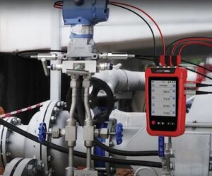
Hydrostatic testing with the Additel 206Ex

Hydrostatic testing (also known as stack testing or a hydrotest) is a method for pressure testing different containment vessels.
Hydrostatic testing is used in a variety of applications.
The most common applications for these tests are:
- Pipelines
- Tanks
- Homeowner use for plumbing
- Natural gas lines
- Fire extinguishers
- Gas cylinders
- Boilers
- Compressors
- Fire suppression systems such as sprinkler systems
- Distribution systems

Compared to other methods of testing the strength of a container, hydrostatic testing is one of the safest tests you can use to find your results. Essentially, hydrostatic testing can check the integrity of a container vessel and also check for leaks in your system.

Hydrostatic testing uses water as the test medium.
medium, which as we know is NOT compressible. If there is a leak in a pipe system or a failed integrity test of the pipes, the result is that water bursts out of that area while very little pressure is applied.
Generally, hydro tests are performed at 1.5x the nominal pressure of the containment vessel. The vessel, pipeline, tank or whatever application you have is partially filled with water and then pressurised to 1.5x the value of the nominal pressure. Most hydro tests take about 8 hours, but it is not uncommon for a test to take up to 24 hours!

Equipment needed

The equipment used to perform these hydrostatic tests is quite outdated and much of it has not changed since hydrostatic testing became the most reliable test for these applications.
not changed since hydrostatic tests became the most reliable tests for these applications. The typical
equipment list for these tests consists of:
- Chart recorders for pressure and temperature
- Lead weight testers
- Pressure relief valve
- A pressure gauge showing the pressure in the pipes

A card recorder? What are you wondering? Traditionally, hydrostatic tests a a card recorder for pressure and temperature to record these measurements. Card recorders were invented in the mid-1800s and were first used for testing in 1915 and the technology has never really never really changed.
Essentially, a chart recorder is a piece of circular paper that rotates in a circle. As the paper rotates, there is a pen for temperature and a pen for pressure. These pens “convey” the temperature and pressure readings for the duration of the test. Many recorders require a key to wind up the clock. wind up, just like your grandfather's clock from 1900! Later, there was a huge advance of the 9v battery to replace the wound coil and that's pretty much where the innovation in this field stopped.

With this 100-year-old testing method, there are many things that can cause an error in this test.
With tests lasting 8 to 24 hours, you really have time to waste on pens running out of ink, technicians losing their paper results, liquid getting on the paper and bleeding your ink, coils needing to be wound up, batteries running out, card storage, etc. Imagine the heartbreak if you pick up your chart after 24 hours and the pen didn't work after hour number 2! Chart recorders are still often used in situations where instant visuals of a test are needed, but perhaps there is no access to power or no access to a computer. However, with today's data recorders reducing cost and power requirements, the chart recorder is fast dying out as the preferred method for these tests. Besides these data recorders, you usually also need a pressure gauge placed in the line and a pressure relief valve.
valve. So wait, are we saying that we no longer need to use 100-year-old technology? Yes indeed!

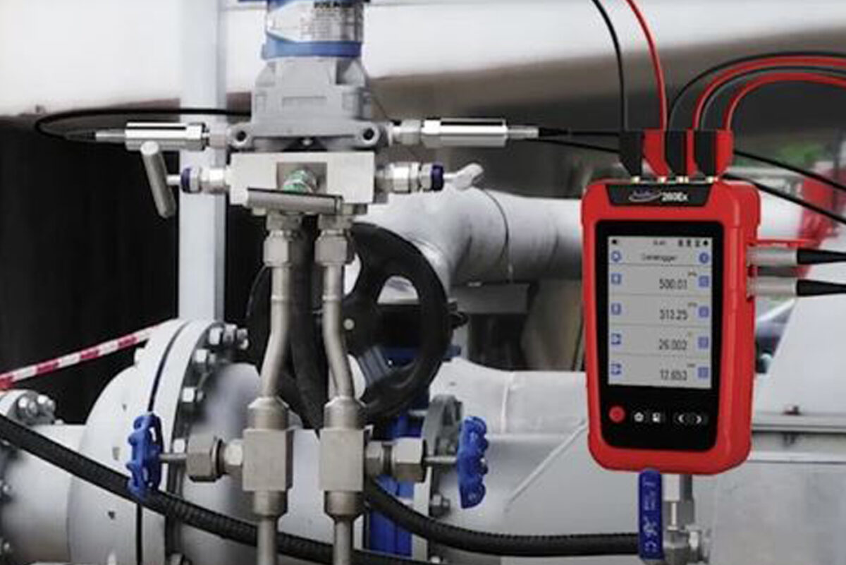
Meet the Additel 260Ex!

This device brings you into the world of running your hydrotests digitally! digital way! Instead of lugging 50lb chart recorders, changing paper and pens, winding up coils and in the rain with a rain with a rubbish bag to cover the chart recorder... now it can all be done digitally and in the palm of your hand. In the digital version of this test, we replace the analogue gauges with our digital pressure sensors.
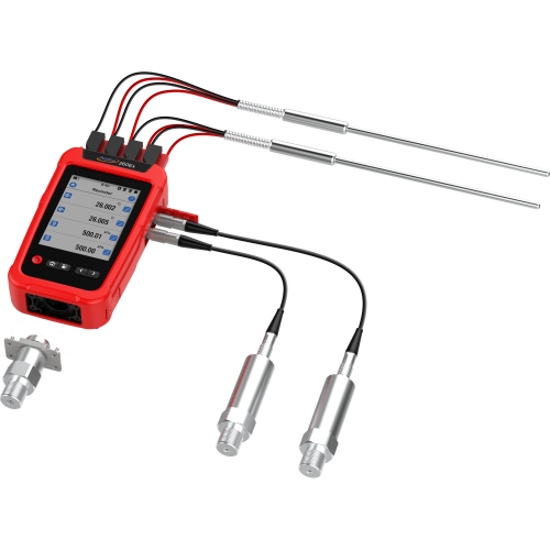
We replace the RTD whose results are stored with pen and paper and use resistance temperature detectors (RTDs). With the Additel 260Ex you can connect 2 RTD devices for your ambient temperature and pipe temperature. You can use the pressure modules to record pressure and pressure and you throw paper charts in the bin and save your results digitally. in the bin and save your results digitally. When you run your hydro test with our 260Ex, this is what you would expect:
- Using the 260Ex pressure module to monitor and store internal pipe pressure
- One RTD for pipe surface temperature
- One RTD for ambient air temperature or soil temperature

Now we record all three parameters of our tests with one device and we do everything at the same time! At the end of your test, simply transfer the results to a PC and print them out.
A huge advantage of our 260Ex is, of course, that you no longer have to carry 300lbs of equipment with you to your test. There are no more lost chart papers and no more spoilt tests, all with more accuracy, more storage space for test results, less cost and a much cheaper annual calibration. the ability to view your test results in real time as they are recorded!
The Additel 260Ex has internal storage for up to 10,000,000 data points, which is more storage space than you will ever need and more than can even be stored on a piece of paper. The Additel 260Ex also connects to our mobile phone app, Additel Link. Now you can view your real-time test results from the cosiness of your truck with the heating or air conditioning on! You can use up to 8 measurement channels on the 260Ex and navigation is a breeze thanks to the 4.4″ LED backlit touchscreen. Is it raining during your test? No worries, the Additel 260Ex has an IP67 waterproof rating.

The ADT260Ex meets the most stringent ATEX, IECEX, CSA and UKCA certifications for intrinsic safety. Each device meets certification level Ex ia IIC T4 Ga. This highly qualified reference recorder can be widely used in environments with potentially explosive gases, such as oil and gas platforms, refineries, chemical and petrochemical plants, the pharmaceutical, energy and gas processing industries. Bring your testing into the 21st century and eliminate failures with our new 260Ex!

Read more
checking the valve position

How to keep control valve positioners in place

Valves, the actuators that move them and the electronic circuits that control them, are designed for intensive daily use. A valve can be moved hundreds to tens of thousands of times over a period of one year. This can cause screws to shift, springs to weaken and mechanical connections to loosen. The valve seat wears out both from the repeated movement of the valve and from the liquid or gas flowing through it.

In addition, electronic components suffer from ‘calibration drift’, causing valves to fail to open or close completely, close prematurely or operate erratically. This results in the gas or liquid flowing through them no longer being regulated properly.

To avoid this, it is important to establish a preventive maintenance programme where the positioners are regularly checked in the field. These checks should be carried out quickly to minimise downtime. When calibration drift occurs, a quick recalibration should be performed.

Six steps for checking valve position

The following are the basic steps for checking the valve position. Always refer to the valve manufacturer's specific instructions for testing and calibrating the positioner.

1. Setting
Set the Fluke 789 Set ProcessMeter in source mode using the appropriate current range for the positioner.

Connect the test leads to the mA source outputs on the Fluke 789.
Select the 4-20 mA range by turning the rotary knob from Off to the orange upper mA output position.
Connect the Fluke 789 to the inputs of the valve.

2. Testing the closing of the valve
To determine whether a positioner closes the valve completely at the 4.0 mA current level.

Set the source current to 4.0 mA on the Fluke 789 ProcessMeter by pressing the 0% button under the SpanCheck button.
While checking that the valve moves, press the Coarse Down button once to reduce the current to 3.9 mA. The valve should not move.
Adjust the zero setting on the positioner to set the valve for the desired closure.

3. Testing the opening of the valve
To check valve opening, press the Coarse Range button when the current source is set to 4.0 mA. The Fluke 789 ProcessMeter increases the current by 0.1 mA with each press of the Coarse Range button.

Note: When setting the point at which the valve starts to open, make sure that the actuator does not exert back pressure against the force holding the valve closed when 4.0 mA is applied to the controller input.

In a spring-closing valve, no pressure should be applied to the diaphragm.
In a double-acting piston actuator, no pressure may be applied to one side of the piston.
You can set the point at which the valve starts to open between 4.1 and 4.2 mA to ensure no back pressure is applied against the forces at the closed setting.

4. Range position testing
Range position testing involves testing the valve in the fully open position.

Press the SpanCheck 100% button, which moves the source current to 20 mA. Use the range buttons on the Fluke 789 ProcessMeter to adjust the source current for a reading of 20 mA and wait for the valve to stabilise.
While visually checking or sensing the valve movement, press the Coarse Up button once to 20.1 mA.
Use the Coarse knob to adjust the current up and down between 20.1 mA and 19.9 mA. The valve stem should not move between 20.1 to 20 mA and move slightly between 20 mA and 19.9 mA.

5. Linearity testing
For valves with linear operation.

Set the Fluke 789 ProcessMeter to 4 mA.
Use the % Step button to increase the current to 12 mA (50%) and confirm that the valve position indicator is at 50% of stroke.
Note: If your valve is not linear, refer to the valve manual for proper operation.

6. Testing smooth operation of valve
Set the rotary switch to the lower mA output and select the Slow Ramp function with the blue button.
Run the Fluke 789 ProcessMeter through several cycles while visually checking or feeling that the valves are operating normally. The valve should NOT rock or chase any of the Slow Ramp step positions, nor move slowly.
Adjust the gain of the valve regulator to the point that gives the best response between these two conditions.

Five ways Fluke Connect features improve positioner testing in the field
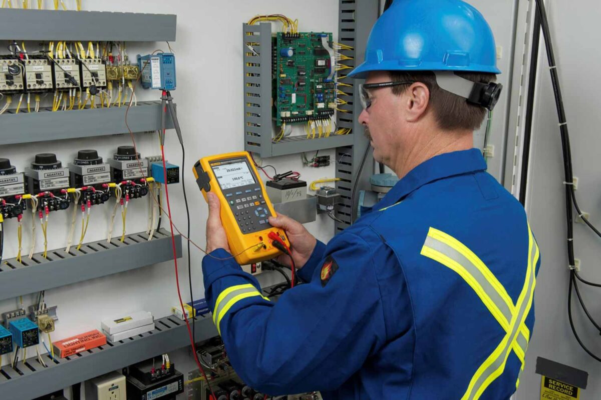
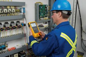
The Fluke 789 FC ProcessMeter and temperature kit offers all the power and capabilities of the Fluke 789 ProcessMeter and the FC connector that gives you access to all the capabilities of the Fluke Connect app on your smartphone, including the ability to:

1. Archive measurements with the EquipmentLog™ history feature in Fluke Cloud™ storage for documentation and future reference in the field.

2. Compare real-time measurements with historical data.

3. Contact other technicians and your manager via a ShareLive™ video call function to show them exactly what you see and get instant feedback.

4. Stay further away from hazardous environments by placing the Fluke 789 FC ProcessMeter at the valve and viewing the results on your smartphone.

5. View digital product manuals, application advice from Fluke and other field resources via your smartphone.

Read more
calibration of equipment

How calibration helps optimisation

Fluctuating commodity prices make it challenging for companies to adjust to the times and maintain good profit margins. One way to control costs across industries is to become leaner and more efficient.

And one of the best ways to control these costs is to find the waste in your process. With regard to instrumentation, this means making many precise adjustments to achieve just the right the temperature and pressure for high-quality production and efficient use of resources.

Equipment calibration leads to better optimisation and higher quality. This also applies to other sectors of the process industry, be it the chemical process industry, nuclear industry, pharmaceutical industry or pulp and paper industry. Manufacturing plants for the process industry use hundreds or even thousands of sophisticated devices that constantly perform countless critical operations in an accurate and reliable manner. These devices themselves also need regular inspection, testing, calibration and repair.

Over the centuries, the importance of carefully recording the details of these inspections, tests, calibrations and repairs has become clear. It is not just a best practice; companies and governments often have highly specific administrative requirements to ensure that customers receive products of the highest quality and the health and safety of citizens are protected.

However, traditional testing, calibration and documentation processes are labour-intensive; because experienced users are scarce, downsized teams sometimes choose to postpone regular calibrations. The latest industry findings suggest that it is feasible for smaller teams to perform and document equipment calibrations at a lower overall cost, with greater productivity and operational reliability benefits.

Calibration of equipment is usually performed at the site of the device (in-situ calibration, from Latin for ‘in place’) or in an instrument workshop.

Professional tip:

During production of a field instrument, both the primary element and the transmitter (or actuator, if a control valve) are calibrated at the factory and calibration information is supplied with the unit. This calibration data is often lost. Entering this information into centralised calibration data as soon as the unit is put into service should be part of standard work and not just done to increase efficiency.

By centralising calibration information, the knowledge stays with the facility even if the teams change.

Most field instruments consist of two parts: a primary element and a transmitter.

  • Primary elements include flow tubes, measuring flanges, pressure sensors, wet chemical sensors such as pH, ORP and conductivity probes, level gauges of all types and temperature sensors. Primary elements usually produce a signal - usually voltage, current or resistance - proportional to the variable they measure, such as level, flow, temperature, pressure or chemical composition. Primary elements are connected to the input of field transmitters.
  • Field transmitters include pressure, temperature and flow devices. They process the signal generated by the primary element by first characterising it in linear form and applying unit of measurement coefficients to it. The signal is then transmitted in analogue (usually 4-20 mA DC) or digital form (usually a variety of fieldbuses).

calibration of equipmentAnalogue devices

Analogue devices, often called ‘4 to 20 mA loop devices’, are so called because they transmit a signal that is an electrical “analogue” representation of a measured physical quantity (e.g. temperature). They transmit an electric current that is proportional (analogue) to the magnitude of a measured physical quantity, with 4 mA representing the minimum scaled value and 20 mA the maximum scaled value.

Although many aspects of systems are now digital, analogue devices are still used in the process industry.

Digital devices

Digital devices convert a measured physical value into a digital signal. Many different digital coding methods are used in the process industry, including Foundation Fieldbus, Profibus and HART.

It is widely believed that (digital) fieldbus devices do not need to be calibrated. However, this is not true. Although a fieldbus signal (whether Foundation Fieldbus, Profibus or connected HART) provides diagnostic information, it does not provide any information about the accuracy of the device, nor does it check whether the device provides an accurate representation of the process.

Top 3 calibration tools to keep your processes lean

1. Additel ADT227 multifunction documenting calibrator with HART functionality and automated calibration procedures; the ADT227 is also available in ATEX version.

2. Additel ADT760 Automatic precision pressure calibrator with documenting function and HART functionality

3. Fluke 754 multifunctional documenting calibrator with HART functionality and automated calibration procedures; the calibrator naturally complies with strict safety standards.

Control valves

Control valves have actuators that also need to be calibrated to compensate for wear and tear and the effects of valve sticking and when the valve has been resealed to correct leaks. Often, when these valves are not operated regularly, a stroke test or partial stroke test must be performed for them to ensure reliable operation.


Ask our experts for advice

Permits and paperwork

Administrative tasks, from applying for permits to documenting and archiving results, can add significantly to the cost and time required for even an in situ calibration. As Ian Vergebeuren of Industrial Automation Networks and a former chair of the Fieldbus Foundation User Group says, “In many cases, getting all the necessary paperwork (permits, isolation, etc.) takes longer than the work itself.”

Challenges in documenting calibrations

Documenting a calibration has traditionally meant manually recording the date and time, pre- and post-calibration values and other comments made by mechanics in a logbook. Surprisingly, many companies continue to document calibration data manually. But handwritten documentation is far from ideal.

Firstly, the likelihood of errors is higher. Handwritten data is often illegible or incomplete. Facilities using a computerised maintenance management system (CMMS) then have to take into account the extra time required to enter handwritten data, which adds another risk of errors.

Changes within workforce

Another challenge for calibration is a change in the workforce.
The 1980s saw budget cuts and layoffs. Countless engineers, maintenance workers and operational staff were laid off following a new lean manufacturing philosophy that is still followed today, especially in developed economies.

Smaller teams have less time for on-the-job mentoring and training, to the point where employees have no time to transfer their equipment- and system-specific knowledge. Once older operators and engineers retire, they take their equipment and systems knowledge with them.

“Every day at 16:00, virtually all plant knowledge walks out the door, and sometimes for good,” says the Chief Instrumentation and Controls Engineer at a large refinery in the Midwest.

Meanwhile, many companies still need two technicians for each in-situ calibration: one at the transmitter and one at the control system. The Fieldbus Foundation estimates that two technicians require a minimum of two hours for commissioning.

calibration of equipmentUse multifunction documenting calibrators
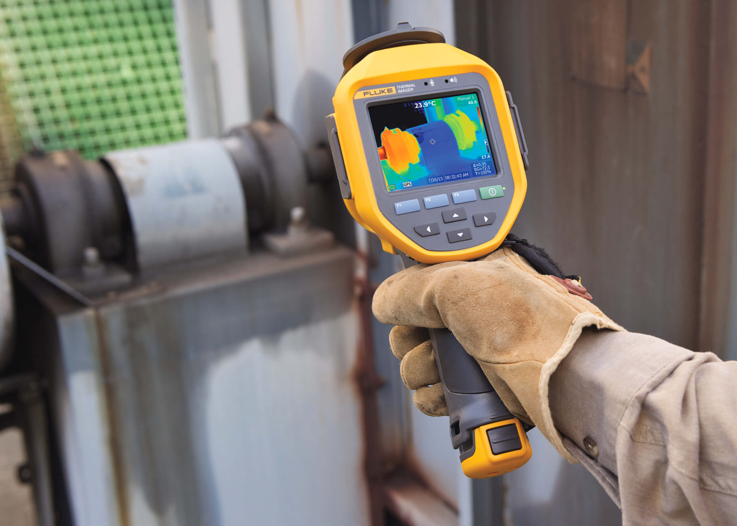
A new generation of ‘smarter’ field calibrators increases employee productivity by combining multiple instruments into one and offering features that go beyond basic testing and measurement, including help with analysis and documentation.

Multifunctional documenting process calibrators are portable, electronic test and measurement instruments that combine multiple calibration steps and functions in one device, simulating and measuring pressure, temperature and a wide range of electrical and electronic signals.

Advantages:

  • Technicians need to master fewer instruments and take them into the field
  • Same calibration processes and data output on multiple devices instead of having to follow a different process for each instrument to collect a different set of data
  • Automated procedures replace many manual calibration steps
  • No second technician is needed to record the ‘as found’ and ‘as left’ status of the field instrument.
  • Faster calibration time per device
  • Calculate the error of one instrument instead of adding up the errors of different instruments

Use calibration routes

With a documenting calibrator, the greatest savings can be achieved by using the route management function integrated into the instrument. Using one set of permits and paperwork for a full set of calibrations significantly reduces costs.

Implement an asset management, calibration management or computerised maintenance management system (CMMS)

Unlike paper documentation, data on the calibrator are never illegible, inaccurate or incomplete. Calibrator data can be downloaded directly to various CMMS systems without transcription or archiving.

Documenting process calibrators automatically capture on-site ‘as-found’ and ‘as-left’ status of each field device and can be operated by a single technician. As a result, using route-based procedures on documenting calibrators can reduce the time and cost required by as much as 50% compared to traditional manual single-device calibration methods. In other words, the same lean team can perform twice as many calibrations in the same period of time.

Running a lean team according to traditional operational requirements undoubtedly leads to mistakes. Calibrations are simply not carried out as they should be. Instead of ignoring the threat, explore how existing activities can be run more efficiently.

Implement route-based calibration, paperless documentation and CMMS data management. More calibrations are performed more accurately, knowledge is transferred from one person to the team and the company, and both productivity and quality increase.

Calibrating multiple instruments during a route reduces the cost per calibration compared to calibrating individual instruments separately.

In addition, millions can be saved on maintenance costs, legal fees and the cost of lost revenue due to accidents. Good calibration procedures help reduce the likelihood of such incidents. In the event of an emergency or legal action, companies can defend themselves with accurate calibration data, whereas this is a lot more difficult when calibration data is not in order.

Read more

Need advice?

Contact our product specialist Thiara for help in choosing the right instrument.
Contact Thiara