Archives for Knowledge centre

calibration additel

Automate, record, and eliminate errors. Automate and maximise efficiency!

Calibration is a crucial process in various industries, essential for maintaining product quality, safety, and durability. Although regular calibration is a standard task, the importance of accurate documentation is often underestimated, mainly due to time constraints or the pressure of other daily tasks. In certain situations, documentation is performed manually, which is not only a time-intensive process but also increases the risk of human error during and after calibration.

Additel calibration

By using calibration tools with automatic documentation functions, you can address these challenges efficiently. These instruments automatically record all test results and provide instant pass/fail indication. Moreover, they enable you to transfer calibration data to calibration management software, reducing the risk of errors and improving the integrity of calibration results.

Benefits of an automatic documenting calibrator:

  • Time saving: Automatic storage of calibration results and execution of calibration procedures save valuable time.
  • Efficiency: Manual transfer of results is unnecessary, saving time and resources.
  • Accuracy: Reduces the risk of errors and increases the consistency and quality of calibration results.
  • Complete traceability: Provides a fully traceable calibration system for your entire organisation.

Discover the advantages of an automatic calibrator compared to the traditional calibration method:

Watch it in the following video:

Wondering which calibrator is right for you? Then ask our expert advice.

Read more
Fluke thermal cameras

10 things you need to know about thermal imaging cameras

Whether you have a simple point-and-print model or a highly sophisticated thermal imaging camera with all possible options; you should consider the following features and specifications:

1. Resolution

    • Detector resolution is the number of detector pixels of the camera. More pixels means higher resolution.
    • Spatial resolution is based on the detector pixels and the FOV, combining them to define the image seen by the camera at a given time. Spatial resolution can be used to define the smallest detectable object size. Lower spatial resolution means more detail and higher image quality.
Fluke thermal imaging camera

2. Focus

When choosing a focusing mechanism, it is important to consider your skills and application. These are the most popular focusing systems:

    • Fixed: Just point and print
    • Manual: Precise step-by-step focusing
    • Auto focus: Automatically focuses on an object but may require manual adjustment.
    • Laser-controlled automatic focusing: Uses an integrated laser rangefinder to calculate the distance to the object.
    • Multifocal: captures multiple images of the object with different focus depths and uses software to combine them into a single image with an extremely sharp depth of field. At Fluke Corp. for example, this technology is called MultiSharpâ„¢ Focus.

3. Temperature range

The highest and lowest temperature you determine during your inspection determines the temperature range you need for your thermal imaging camera. You can select a camera with a wide temperature range that automatically determines the range based on your frame, or allow you to select the temperature range manually.

4. Lens options

With a camera with interchangeable lenses, you are more versatile, allowing you to inspect many more types of installations and situations. There are plenty of choices for numerous applications: standard, wide-angle, telephoto and macro.

5. Saving images and associated data

Save infrared images and digital images (sometimes with voice notes) to internal memory, a removable SD card or a USB stick. It is important to have the flexibility to save images and additional associated data to different media for backup or sharing.

6. Colour palettes

Subtle differences are more quickly noticed in a monochrome display such as greyscale or amber. High-contrast palettes make it easier to quickly identify obvious discrepancies. You can change the palette in the camera or in the software.

7. Colour arms

Use it to quickly mark areas outside normal temperature ranges.

8. Emissivity and reflected temperature

Surfaces with low emissivity, such as shiny metals, can reflect infrared energy from other objects and affect your image and measurement accuracy. So look for the option to adjust parameters when choosing a thermal imaging camera.

9. Spot marks

Highlight specific temperatures on your image to simultaneously compare temperatures of multiple points in the same image.

10. Battery type and lifetime

Look for a battery with useful features such as a charge status indicator. Nothing is worse than starting an inspection without knowing the battery status. Also consider battery life and fast-charging capacity.

Need help choosing the right model?

Read more
Fluke thermal imaging camera

Everything you need to know about thermography and thermal imaging cameras

A thermal imaging camera is an inspection tool that captures infrared energy - radiation emitted by an object - and creates an image. Thermal imaging cameras, also known as infrared cameras and thermographic cameras, are ideal for industrial inspection. Maintenance, leak detection and machine troubleshooting are all common applications. 

What is a thermal imaging camera used for? 

Thermal imaging cameras can be used for a wide range of applications: building inspection, security, electrical maintenance, firefighting, gas detection and more. Thermography is a particularly powerful testing method for use in situations where: 

  • Remote inspection essential for safety 
  • Damage or decay is expressed by temperature changes, as in three-phase wiring 
  • Test objects/subjects are invisible due to poor visibility 
Hikmicro M30 thermal imaging camera

What is thermography? 

Thermography is the process of capturing infrared radiation and translating it into thermal images, or thermograms. Thermography shows variations in temperature expressed in colour. Powerful infrared cameras are incredibly sensitive and show heat in great detail with colour gradations. 

 Everything around us emits infrared energy - a heat signature. Thermography works by measuring infrared energy and converting that data into electronic images representing surface temperature. An optical system focuses infrared energy on a sensor array, or detector chip, with thousands of pixels in a grid. A matrix of colours corresponding to temperatures is sent as an image to the camera display. 

Read more
What is a diode

What is a diode?

What is a diode?

A diode is a semiconductor component that forms a kind of one-way switch for current. It allows current to flow easily in one direction, but hardly at all in the opposite direction.

Diodes are also called rectifiers called diodes, because they convert alternating current (AC) into pulsating direct current (DC). Diodes are classified according to type, voltage and current capacity.

Diodes are polar: they have a anode (positive side) and a cathode (negative side). Most diodes allow current to flow only when positive voltage is applied to the anode. Different diode configurations are shown in this figure:

Diodes are available in different configurations. From left to right: metal housing, screw diode, plastic housing with band, plastic housing with chamfer, glass housing.

When a diode allows current passage, it is polarised in the forward direction. When a diode involves preload in the locking direction, it acts as an insulator and does not allow power passage.

Strange but true: The arrow of the diode symbol points in the opposite direction of electron emission. Reason: The symbol was devised by engineers and in their schematic representation, current flow proceeds from the positive (+) side of the voltage source to the negative (-). The same convention is applied for semiconductor symbols in which arrows are used: the arrow points in the ‘usual’ permitted direction of current flow, and against the permitted direction of electron flow.

In a diode test of a digital multimeter, the diode produces a small voltage between the test wires, which is sufficiently strong to polarize a layer diode in the forward direction. The normal voltage drop is between 0.5 and 0.8 V. The resistance of a properly functioning diode in the forward direction is between 1000 ohms and 10 ohms if all goes well. When there is bias voltage in the reverse direction, the display of a digital multimeter the value OL is displayed (this indicates a very high resistance).

Diodes are rated for a specific current rating. If this is exceeded and the diode fails, a short circuit may occur and a) current may flow in both directions or b) current may be stopped in both directions.

Reference: Digital Multimeter Principles by Glen A. Mazur, American Technical Publishers.

Read more
What is the duty cycle?

What is the duty-cycle?

What is Duty-Cycle?

What is the duty cycle?

The duty cycle is the ratio of the duration that a load or circuit is ON to the duration during which the load or circuit is OFF.

The duty cycle, sometimes called ‘duty factor’, is expressed as a percentage of the ON time. A duty cycle of 60% indicates that a signal is ON 60% of the time and the remaining 40% OFF.

what is duty-cycle?


Many loads are quickly switched on and off via a fast-acting electronic switch that accurately manages the output power of the load. Load operation-such as the brightness of a lamp, the output of a heating element and the magnetic strength of a coil-can be controlled on a duty-cycle basis via periods of ON and OFF or cycles per second.


Duty-cycle simplified

If the atomiser is pulsed ON with varying duration (this is called pulse width modulation), the duty cycle is always different. If the atomiser is pulsed ON for 0.05 second in a 0.1 second cycle, the duty cycle of the fuel atomiser is 50%. If the atomiser is pulsed ON for 0.09 second of the same 0.1 second cycle, the duty cycle of the fuel injector is 90%.


Example of duty-cycle

In a car electronic fuel injection system, voltage pulses fed to the fuel injection valve solenoid control the fuel injection valve at a fixed rate of 10 cycles per second or 10 Hz.

Pulse width modulation allows precise electronic control of the fuel supply to the motor. The average voltage for each duty cycle is determined by the amount of pulse time ON.

Duty-cycle controlled solenoid valves use a variable duty-cycle signal to vary the flow or adjust the pressure. The longer a solenoid valve stays open, the greater the flow and the lower the pressure built up. These solenoid valves are controlled by the power supply or ground.


What is pulse width?

Pulse width is a measure of the actual duty cycle in milliseconds. The time OFF does not affect the pulse width of the signal. The only value measured is how long the signal is ON (controlled by the ground).

Reference: Digital Multimeter Principles by Glen A. Mazur, American Technical Publishers.

Read more
What is Ohm's law?

What is Ohm's law?

What is Ohm's law?

The Ohm's law is a formula used to calculate the relationship between electric voltage, electric current and resistance in a circuit.

For people learning about electronics, Ohm's law, U = I x R, is as important as Einstein's theory of relativity (E = mc²) is for physicists.

U = I x R

Written out, this means voltage = current x resistance, or volt = amp x ohm or V = A x Ω.

Ohm's law, named after the German physicist Georg Ohm (1789-1854), relates to the most important quantities in circuits:

GreatnessSymbol for the way of OhmUnit of measurement (abbreviation)Role in circuitsIn case you were wondering:
TensionUVolt (V)Pressure activating the flow of electronsU = urgere (Latin for ‘to propel’)
CurrentIAmpere, amp (A)Speed of electron flowI = intensity
Resistance ROhm (Ω)Inhibits flowΩ = Greek letter omega

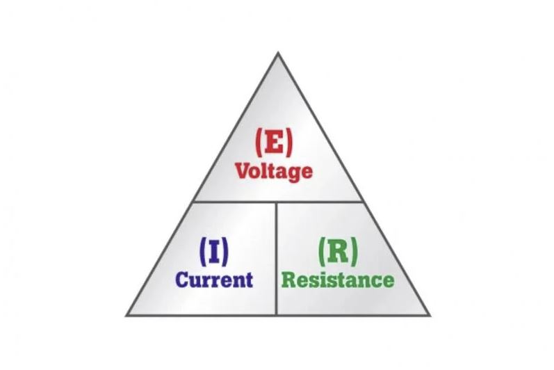
If two of these values are known, engineers can use Ohm's law to calculate the third. The pyramid can be changed as follows:

What is Ohm's law

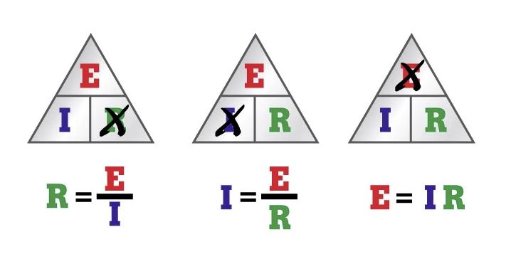
If the voltage (E) and current (I) are known and you want to calculate the resistance (R), cross out the R in the pyramid and calculate the remaining equation (see the first pyramid, on the far left, above).

Remark: resistance cannot be measured when a circuit is in operation. Ohm's law is then especially useful if it needs to be calculated. It is not necessary to switch off the circuit to measure the resistance, because using the above variation on Ohm's law, a technician can calculate R.

If the voltage (E) and resistance (R) are known and you want the stream (I), cross out the I in the pyramid and calculate the remaining equation (see middle pyramid above).

If the current (I) and resistance (R) are known and you want the tension (E) calculation, multiply the two values at the bottom of the pyramid by each other (see the third pyramid, far right, above).

Try some example calculations for a simple serial circuit with one voltage source (battery) and resistor (bulb). In each example, two values are known. Use Ohm's law to calculate the third.

Example 1: Voltage (E) and resistance (R) are known.

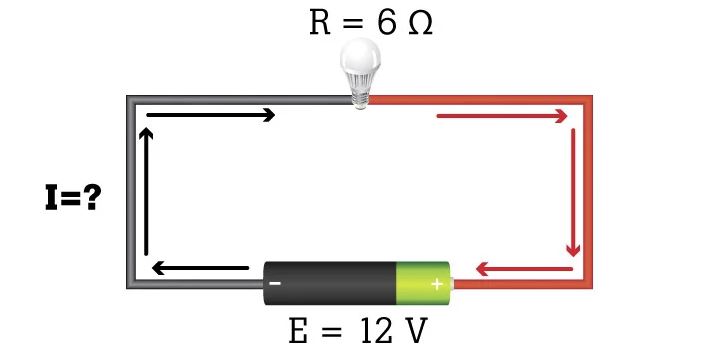
What is the current in the circuit?

I = U/R = 12 V/6 Ω = 2 A

Example 2: Voltage (E) and current (I) are known.

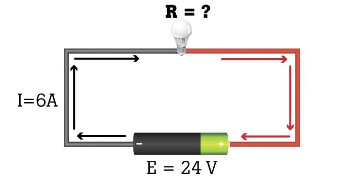
What is the resistance caused by the bulb?

R = E/I = 24 V/6 A = 4 Ω

Example 3: Current (I) and resistance (R) are known. What is the voltage?

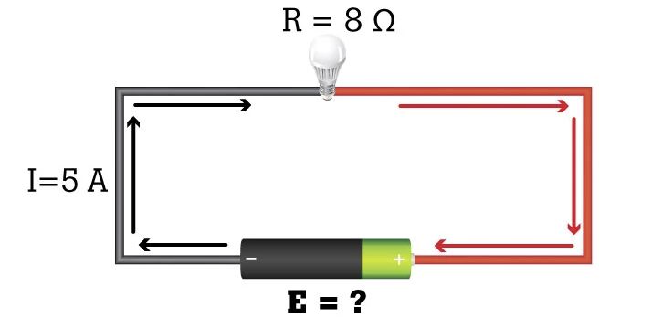
What is the voltage in the circuit?

E = I x R = (5 A)(8 Ω) = 40 V

When Ohm published his formula in 1827, his main conclusion was that the amount of electric current flowing through a conductor was directly proportional is with the voltage to which it is subjected. In other words, it takes one volt of pressure to push one ampere of current through one ohm of resistance.


What can be validated with Ohm's law

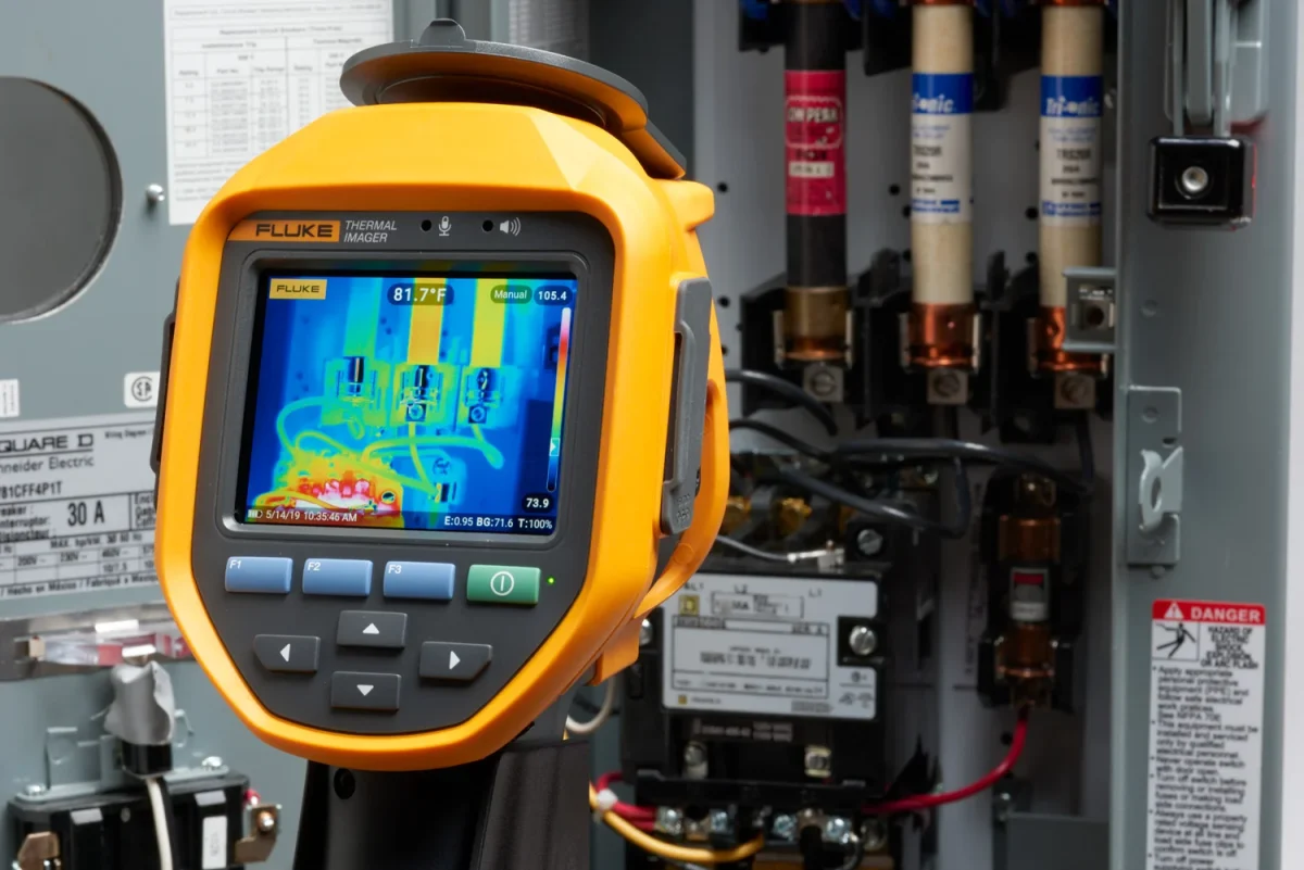
Ohm's law can be used to validate the static values of circuit components, current levels, voltage inputs and voltage drops. For example, if a measuring instrument observes a higher current reading than normal, it may mean that resistance has decreased or voltage has increased, causing a high-voltage situation. This may indicate a problem in the power supply or with the circuit.

In direct current (DC) circuits, a lower than normal current measurement value may mean that the voltage has decreased or the circuit resistance has increased. Possible causes for increased resistance are poor or loose connections, corrosion and/or damaged components.

Loads in a circuit take electrical current. Loads can be all kinds of components: small electrical appliances, computers, household appliances or a large motor. Most of these components (loads) have a rating plate or information sticker. This shows the safety certification and various reference numbers.

Technicians consult component nameplates to find out what the standard voltage and current values are. If, when measuring, a technician finds out that the digital multimeter or current clamp registers different values from the usual ones, he/she can use Ohm's law to determine which part of the circuit is not working properly and what could be causing it.


Basic knowledge about circuits.

Like everything else, circuits are made up of atoms. Atoms, in turn, are made up of subatomic particles:

  • Protons (with a positive electrical charge)
  • Neutrons (no charge)
  • Electrons (with a negative charge)

Atoms are held together by the forces of attraction between the nucleus of the atom and the electrons in the outer layer. When atoms in a circuit are exposed to voltage, they re-form and their parts exert an attraction potential known as a potential difference. Loose electrons with mutual attraction move towards protons, creating an electron flow (current). Any material in the circuit that interferes with this current is considered resistance.

Reference: Digital Multimeter Principles by Glen A. Mazur, American Technical Publishers.

Read more

What is True-RMS?

A true-RMS-device (RMS = Root Mean Square) is one of three instruments used to calculate alternating current (AC) or AC voltage:

  1. True-RMS digital multimeter (or clamp meter)
  2. Medium-response true-RMS digital multimeter (or clamp meter)
  3. Oscilloscope

Only the first two instruments are commonly used and both can measure accurate standard (pure AC) sinusoidal waveforms.

This does not alter the fact that a true-RMS meter is widely preferred because only it can measure both sinusoidal and non-sinusoidal AC waveforms. (See the illustrations at the top of the page.)

  • Sinusoidal (sine) waves: Clean, without distortion, with symmetrical transitions between peaks and troughs.
  • Non-sinusoidal waves: Waves with distorted, irregular pattern ejections, pulse trains, squares, triangles, sawtooth shapes and other ragged or angular shapes.

Calculate RMS

As mentioned earlier, RMS for Root Mean Square. Although understanding this formula can be challenging, RMS basically calculates the equivalent direct current value of an AC waveform. In more technical terms, it determines the ‘effective’ or DC heating value of any AC waveform.

A meter for average values uses mathematical formulas to average for accurate measurement of pure sine waves. It can measure non-sinusoidal waves, but with uncertain accuracy.

One more advanced true-RMS meter can accurately measure pure waves and the more complex non-sinusoidal waves. Waveforms can be distorted by non-linear loads, such as frequency-controlled drives or computers. If an attempt is made to measure distorted waves with an averaging meter, the meter's calculations may be up to 40% too low or 10% too high.

What-is-true-RMS

Where to measure true-RMS

The need for true-RMS meters has increased as non-sinusoidal waves have become increasingly common in circuits in recent years. Some examples:

  • Frequency-controlled motor drives
  • Electronic ballasts
  • Computers
  • HVAC
  • Semiconductor environments

In these environments, current is present in short pulses instead of the smooth sine waves drawn by a standard induction motor. The waveform of the current can have a great effect on the readout of current clamps. In addition, a true-RMS meter is a better choice for making measurements on electrical lines where AC characteristics are not known.

Reference: Digital Multimeter Principles by Glen A. Mazur, American Technical Publishers.

Read more
Inspecting electrical systems

How infrared cameras help you do your job safely

Inspecting electrical systemsIf you are servicing or troubleshooting industrial machinery, your safety depends partly on your environment and partly on yourself. You want to inspect electrical systems or check that equipment is operating within specifications to prevent damage or injury from overheating, misalignment or power quality problems. You are responsible for keeping equipment running correctly and you want to check that equipment from a safe distance and look for faults.

A infrared camera can help you on both counts. With thermal imaging cameras you can scan equipment, structures and processes from a safe distance, reducing exposure to safety risks. In some cases, this means you no longer need a hot work permit.

These are some areas where a thermal imaging camera increases your safety:

  1. Inspecting electrical systems

    With an infrared camera, you can stand well outside the arc zone and scan live equipment using special infrared beams without having to open the panel. This can reduce your risk and may also mean putting on less personal protective equipment (PPE).

  2. Potentially explosive environments

    A thermal imaging camera with telephoto lens allows you to stand further away from the equipment in a potentially explosive environment and still capture all the necessary details. By scanning from a great distance, you do not have to climb into towers, on chimneys or air filters to inspect areas that you would otherwise not be able to get close enough without shutting down production.

  3. Building inspection

    Thanks to the remote capabilities of a thermal imaging camera with a telephoto and/or wide-angle lens, you can scan a lot of ceilings, roofs or walls and pipes from the ground. This reduces the risk of falling and speeds up your inspections.

Read more
personal protective equipment (PPE) for thermographers

Arc safety and thermal imaging

The National Fire Protection Association (NFPA) 70E standard for electrical safety in the workplace has already come a long way regarding personal protective equipment (PPE) for thermographers (people who use infrared cameras).


In the past NFPA 70E cycles, thermographers and their employers have been pushing to change the requirements for spark-arc resistant clothing and PPE for performing an infrared scan. And there are reasons to complain.

In a paper submitted to the 2008 IEEE/IAS/ Electrical Safety Workshop1 , Vladimir Ostrovsky noted that such equipment (especially the hood) restricts the oxygen supply for the wearer, which increases the feeling of claustrophobia and causes breathing difficulties. Although ventilation systems can reduce this discomfort, thermographers still struggle to take good thermal images due to limited light conditions, the hood's limited viewing window and the use of their infrared camera in combination with the heavy gloves.

During the review of NFPA 70E proposals in 2009, 2012 and 2015, several

people and companies proposals for thermal imaging and the 70E committee once again discussed their approach to the problem.

The following questions were addressed:

  • What are the real risks of thermography?
  • Will the thermographer remove the equipment housing under power or will someone else perform this task?
  • Will the thermographer interrupt the field of the enclosure?
  • Was there a risk of contact or parts going live in the equipment?
  • How close will the thermographer get to the potential source of spark arcs?
  • Is the person performing the scan a qualified electrician in accordance with OSHA and NFPA 70E?

In the 2015 NFPA 70E, the committee ruled that if the person removing the enclosure is wearing spark-resistant clothing and PPE, the thermographer need not do so provided:

  • The thermographer does not enter the unauthorised area,
  • Does not interrupt the housing field; or
  • Do not operate or touch the equipment in any way.

One of the main questions the committee had to address was whether or not thermographers qualify. We decided that OSHA and NFPA 70E require anyone exposed to the hazards to be eligible for qualification. Therefore, the 70E committee decided it was acceptable to allow electrically qualified persons the flexibility to perform their duties in a safe manner. Since we cannot be present at every site, that decision must be made by the qualified person doing the work.

Time to decide

It is important to note that NFPA 70E stands for minimum safe practices, not recommended procedures. Any qualified person wishing to perform a task that exposes them to electrical hazards must carry out a full risk assessment, including an assessment of the risk of electric shock and electric arcing. At first glance, this may seem confusing and contradictory. On the one hand, NFPA 70E does not mandate spark arc-resistant PPE and clothing while performing an infrared scan. On the other hand, the technician may find that PPE may be required in his or her specific case even though it is not required by NFPA 70E.

The 70E Committee considers that as long as the equipment is live, the risk of arcing remains. In Table 130.7(C)(15)(A)(a), we note that spark-arc resistant PPE may or may not be required depending on the tasks and conditions. Spark-resistant PPE may be required for personal safety even though it is not required by NFPA 70E. As mentioned earlier, 70E represents the minimum acceptable requirements and there is a possibility that these requirements may need to be exceeded. This is an example of why the user of NFPA 70E should know the entire Chapter 1 if performing tasks on electrical equipment.

There are no exceptions: ignoring the risks associated with a task under NFPA 70E will only result in you ending up in a burn centre sooner. Nobody wants to end up there. This is an area where being lazy can change the thermographer's life forever.

In addition, the person removing the enclosure must wear full spark-resistant clothing and PPE. Once the enclosure has been removed, the area secured and checked for potential hazards, the thermographer can enter and perform the scan with the PPE required for that level of risk.

Summary

Wearing spark-resistant clothing and personal protective equipment (PPE) for thermographers may now become a personal decision in some cases. Remember that OSHA requires employers to provide PPE and employees to wear such PPE if there are hazards. A hazard/risk analysis can indicate whether such PPE is necessary and this analysis should be properly recorded.

Consider the following questions when deciding whether or not to wear personal protective equipment (PPE) for thermographers:

  • What would your life be like after a serious spark incident?
  • What would follow for your family and friends? How would your life change if you were maimed or disabled?
  • How sure are you that there are no defects in the equipment you are about to scan?

The NFPA 70E committee (and I) sincerely hope (hope) that no one ever finds themselves in a situation where they have to answer these questions because of an electrical incident. If it is really inconvenient to wear the required PPE or if there is simply no room, a viewing window can be considered.

Read more
safe use of digital multimeters

Manual for safe use of digital multimeters

It has been proven that a well-built digital multimeter under demanding conditions performs better than a second-line model. Not only is a top-of-the-range instrument more resistant to your working environment, but it also helps keep you safe. Once you have a multimeter, safe use of digital multimeters is still important in any environment you work in. Always check that your multimeter is safe to use.


Ask our experts for advice

What are electrical parameters?

Every piece of equipment that uses or moves electricity has a set of electrical parameters. These are classifications and codes, such as CAT specifications and protection classes (IP codes), which are aligned with standards set by specially appointed teams of professionals. Understanding the electrical parameters of a device will help you better understand how to test its performance and how to keep it and yourself (and those around you) safe. Some examples of electrical parameters are impedance, inrush current, power factor and voltage drop.

What are the CAT specifications of the multimeter?

Digital multimeters are suitable for different electrical parameters, so you should check for proper CAT specifications, IP codes and independent verification symbols to ensure that the meter you select has been tested by an independent laboratory and is safe for your measurements.

When determining the correct overvoltage category (CAT II, CAT III or CAT IV) of the installation, you should always select an instrument that is suitable for the highest category in which you can potentially use the instrument and select a voltage standard that is suitable for or exceeds these situations. Meters with a CAT specification are designed to minimise the risk of an arc in the meter. Ratings are usually located near the inputs.

To give an example: if you are preparing to measure a 480-V power distribution panel, you should use a meter that is at least CAT III-600 V compliant. This means that a CAT III-1000 V or CAT IV-600 V may also be suitable in this situation.

Measurement category  Description Examples
CAT IV Three-phase when connected to mains, all conductors outside

Limited only by the mains transformer feeding the circuit

50 kA short-circuit current

  • The ‘origin of the installation’, i.e. where the low-voltage system (cables for service entry) is connected to the mains.
  • Electricity meters, primary overcurrent protection equipment.
  • Outdoor pipes and service entrance, service line from mast to a building, line between meter and panel
  • Overhead pipe to detached building, underground pipe to well pump.
CAT III Three-phase distribution, including single-phase commercial lighting

'50 kA short-circuit current

  • Equipment in fixed installations, such as switchgear and multiphase motors.
  • Bus and power supply circuits in industrial plants.
  • Power supplies and short branch circuits, devices fed directly from distribution panels.
  • Lighting systems in large buildings.
  • Sockets with short connections to the service input
CAT II Loads connected to a single-phase connection.

'10 kA short-circuit current.

  • Household appliances, portable tools and similar loads.
  • Sockets and long branch circuits.
    • Sockets more than 10 metres from CAT III source.
    • Sockets more than 20 metres away from a CAT IV source.

The two-digit IP code indicates your meter's resistance to dust and water. It describes the size of dust particles that are retained and to what depth your multimeter can be submerged while continuing to function.

Degree of protection against ingress of solids

Level Object size Effective against
0 Object size No protection
1 >50 mm A large area of the body
2 <12.5 mm Fingers and the like
3 <2.5 mm Tools, thick cables
4 <1 mm Granular objects. Most cables, screws, etc.
5 Protected against dust Not fully protected, but should not hinder proper operation
6 Dustproof No penetration of dust. Dustproof

The second digit of an IP rating indicates the level of protection against water.

Degree of protection against water ingress

Level Protected against Details
0 Not protected
1 Dripping water Vertical falling water. No harmful effect
2 Dripping water, 15° tilt Vertical falling water. No harmful effect when the device is tilted up to 15° from its normal position
3 Spray water Water drops as spray at up to 60°. No harmful effect
4 Splashing water Water splashing from any direction. No harmful effect
5 Water jets Water sprayed through a nozzle from any direction. No harmful effect
6 Powerful water jets Water projected in powerful jets through a nozzle from any direction. No harmful effect
7 Immersion up to 1m Immersion in water up to 1 m for 30 minutes. Waterproof up to 1 m for 30 minutes
8 Immersion deeper than 1m Continuous immersion


Schedule a consultation


At Fluke, we test our products for safety so that they go to the limit. Only when the test team is no longer able to interfere with the instrument's operation can the instrument be released for production. The goal is to ensure that a Fluke digital multimeter can withstand the most demanding real-world conditions time and time again. And that you, the user, remain safe and can return home every day. We also ensure that our products are independently tested to back up our claims.

What are security measures for multimeters?

Safe use of digital multimeters is important. Before taking a measurement with your multimeter, inspect it visually. Check the meter, measurement probes and accessories for signs of physical damage. Make sure that all plugs are tightened securely and look for exposed metal or cracks in the housing. Never use a damaged meter or damaged measuring probes.

After the visual inspection is done, check if your multimeter is working properly. Never just assume it is. Use a known voltage source or a monitoring device, such as the Fluke PRV240, to check that your meter is working properly. This is a requirement of NFPA70E (US) and GS38 (Europe).

Working with electricity always involves risk. Know what these hazards are and take appropriate precautions before you start taking measurements. Be aware of the possibility of spikes such as momentary overvoltages and arcing or sparking.

  1. Always assume that any electrical component in a circuit is live until you have taken the steps to positively discharge it. Shock occurs when the human body becomes part of an electrical circuit. So pay attention to the position of your body when working in electrical environments.
  2. Make sure you use the right personal protective equipment (PPE) in every situation. This means both on the body (i.e. gloves, headgear) and near the body (i.e. insulated rubber mats). These are required when working on or near live and exposed electrical circuits of more than 50V.
  3. Never work alone on or near exposed and live equipment. Stay safe and make sure you and your partner are also aware of the surroundings. If possible, do not perform measurements in damp or wet environments and make sure there are no atmospheric hazards nearby (i.e. combustible dust or vapour).
  4. Finally, keep an eye on the display of your digital multimeter for any visual warnings. It can alert users to irregularities such as unsafe voltages (30 V or higher) at the measurement probes.
Read more

Need advice?

Contact our product specialist Thiara for help in choosing the right instrument.
Contact Thiara