Blog

IEC 61000-4-30 class A

What does the IEC 61000-4-30 Class A standard mean for me?

The IEC 61000-4-30 Class A standard eliminates guesswork when choosing a power quality instrument.

Grid power quality logging, measurement and analysis is still a relatively new and rapidly developing field. Whereas fundamental electrical measurements such as RMS (effective voltage) and current have well-defined measurement parameters, many mains power quality parameters have no such definition. This fact has forced leading manufacturers to develop their own algorithms for measuring these mains power quality properties, resulting in hundreds of unique, global measurement methods.

With so much diversity between instruments, technicians often have to take the time to analyse and understand the capabilities and specific measurement algorithms of the instrument in question, rather than understanding the quality of the power supply itself. Standardising measurement methods allows direct comparison of results from different analysers.

Standard IEC 61000-4-30 Class A defines the measurement methods, collection times, accuracy and evaluation for each mains power quality parameter, to obtain reliable, repeatable and comparable results. In addition, the IEC 62586 standard defines the minimum set of parameters to be implemented for mains power quality instruments used in both portable and fixed installations.

As more manufacturers begin to design instruments for measuring and analysing mains power quality to Class A standards, technicians can be more confident in the measurements they take. All this increases accuracy, reliability, comparability and efficiency at work. The standard is updated periodically as the industry evolves and new measurement scenarios are discovered or required. Since its introduction in 2003, the standard has been updated several times and is currently in edition 3 (2015).

Examples of requirements according to class A

The measurement uncertainty of the supply voltage is set at 0.1% of the specified input voltage Udin over the range from 10% to 150% of Udin. It is important to note that in many cases accuracy is only specified at full scale, and while 0.1% accuracy is relatively easy to achieve, it is more difficult to achieve over this wide range.

In addition, the requirement states that measurements must be ‘continuous and non-overlapping’ over a 10/12 cycle for a 50/60 Hz electrical system. It is important to pay attention to this when looking at plant specifications, as units with a high degree of measurement uncertainty can lead to results that can be disputed by the utility or their customer.

Cheap mains power quality measurement systems, for example, often have higher levels of uncertainty when measuring at the lower end of the scale (example: measuring on a potential transformer with phase-to-neutral voltage at 58 volts). In addition, variations can also go unnoticed if measurements are not taken contiguously. These errors can lead to defective equipment being thought to be working properly when in fact it is not. With a Class A certified instrument, a technician can rest assured that measurements have been classified with internationally accepted uncertainty values. This is especially important when checking compliance with regulations or comparing results between different instruments or batches. Functional test and uncertainty requirements for Class A equipment are detailed in IEC 62586-2.

Voltage fluctuations and interruptions should be measured on a full cycle and should be updated every half cycle so that the instrument can combine the high resolution of data points sampled on a half cycle with the accuracy of RMS calculations on a full cycle. Relying solely on full-cycle calculations could misidentify valid conditions, while using only half-cycle calculations may not provide the required accuracy to fully understand any problems.
Collection periods are measurement data compressed by a mains power quality instrument at specified intervals. A Class A instrument shall display data in the following collection periods:

  • The standard time interval of measurement should be a 10/12 cycle (~200 msec) at 50/60 Hz. The interval time varies depending on the actual frequency.
  • 150/180 cycles (~3 sec) at 50/60 Hz. The interval time varies depending on the actual frequency.
  • Interval of 10 minutes synchronised with coordinated universal time (UTC)
  • Interval of 2 hours for Plt flicker

External time synchronisation is required to obtain accurate timestamps, allowing accurate correlation of data between different instruments. Accuracy is specified at ± 20 ms for 50Hz instruments and ± 16.7 ms for 60Hz instruments, regardless of the total time interval. Achieving this accuracy requires either a GPS clock via a GPS receiver or NTP (Network Time Protocol) via Ethernet. When synchronisation per an external signal is no longer available, the timing tolerance should be better than ± 1 s per 24-hour period. However, this wider tolerance is not confirmation that the measurements are Class A compliant. The lack of accurate timestamps in cheaper mains power quality instruments can make it extremely difficult to accurately troubleshoot mains power quality problems. This can lead to an inability to correctly identify the distribution of voltage events on the network when using multiple instruments.

The FFT algorithm for harmonics is precisely defined so that all Class A instruments end up with the same values of harmonics. The FFT method provides infinite algorithms that can result in very different values of harmonics, if unregulated. Class A requires harmonics to be measured with the same 10/20 cycle as the RMS measurements, according to standard Class I IEC 61000-4-7/2008, using a continuous harmonic subgroup measurement method. IEC 6100-4-7 describes several methods and algorithms for measuring harmonics, but IEC 61000-4-30 specifically mentions the Class I subgroup method.

All of these Class A requirements play an important role in providing accurate, reliable and comparable data to users, ultimately leading to better analysis and troubleshooting of mains power quality problems. With instruments that are not Class A compliant, measured results cannot be easily compared.

Conversely, Class A instruments will actually be consistent and comparable, allowing technicians to work with the confidence required to accurately analyse even the most complex grid power quality problems. For both suppliers and large energy consumers, it is important to be able to monitor incoming mains power quality and identify whether a mains power quality problem is caused inside or outside the energy consumer's premises.

Only instruments specifically designed for troubleshooting, recording and analysing mains supply parameters can provide the detailed information that allows you to pinpoint a fault source and diagnose the problem correctly. Moreover, measurements performed with Class A compliant instruments can be used in legal or contractual disputes. Therefore, it is important to choose an instrument that meets these requirements.

Fluke 1770 series three-phase Power Quality Loggers
Fluke 1738 three-phase Power Quality Loggers
Fluke 1736 three-phase Power Quality Loggers


Read more
improving the power factor

How to improve the power factor

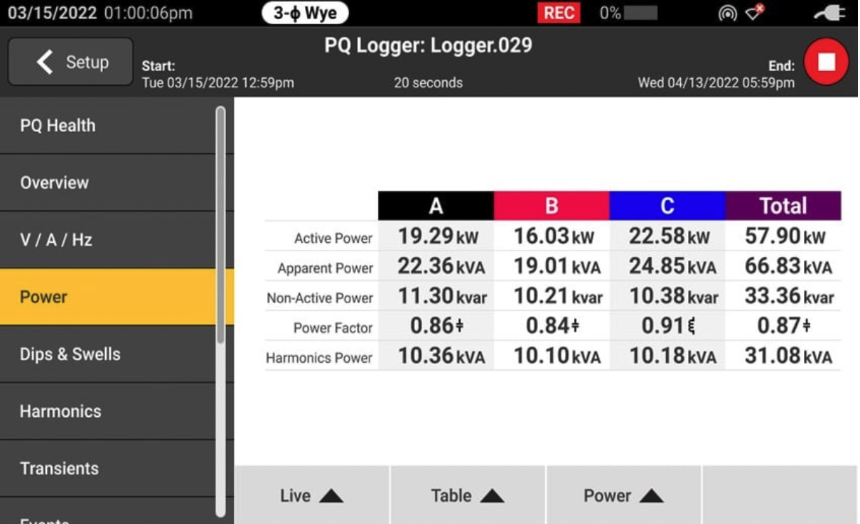
The power factor is, simply put, the ratio of working power to apparent power, or demand power. The power factor is an expression of energy efficiency, with a higher percentage indicating more efficient energy consumption and a lower percentage indicating less efficient energy consumption. To calculate the power factor, divide the working power (kW) by the apparent power (kVA). While an efficiency of 100% may not be realistic, there are a few things that affect it, improving the power factor requires a good strategy.


Ask our experts for advice

What is the ideal power factor?

A low power factor means you are not using the energy you pay for efficiently. Lower power factors require more apparent power (kVA) to produce working power (kW). A higher power factor is better than a lower one because it means you are using energy more effectively. A common target number for the power factor is 95%. Check with your utility company what threshold they use. Many utilities charge customers if they have a low power factor.

Measuring and managing energy consumption

By the measure energy and power quality, you will get a feel for the rhythm of your installation and learn how to keep your plant running smoothly and efficiently. Strategic power management is an important way to reduce your energy consumption and your energy bill. One reason to improve your power factor is to reduce or even eliminate fines and surcharges from your utility company.

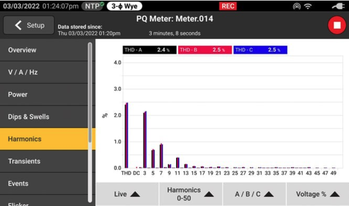
To do that, you need to know where your energy is going each month. First of all, you need to measure and record energy data from your equipment and systems. The type of instrument you need to do this depends on your facility and needs. A multifunctional tool can calculate energy losses and record high-resolution three-phase voltage and current waveforms, while another instrument can provide direct status data of mains power quality. It is important to know the level of harmonics in your power. A THD (Total Harmonic Distortion) measurement can help you figure out whether filtering is needed. And remember that a utility can only affect voltage quality. They can only require approved loads to be connected and are not responsible for the current flowing as a result of the customer's installation.

Steps to a better power factor

Motor inductance and harmonic currents are two common factors that contribute to poor power factor. To improve power factor, determine the root cause of poor power factor.

When dealing with inductive current, adding power factor correction capacitors (energy storage devices) to your plant's power distribution system is a commonly used solution. Power factor correction capacitors require regular inspection and recommended preventive maintenance, but under normal conditions they will operate trouble-free for years.

If harmonics cause the low power factor, cost-effective passive LC filtering (inductor-capacitor) is the solution.

For more complex situations, active filtering is needed. This type of filtering compensates for reactive currents, harmonic currents and unbalanced currents.

A common mistake is to use capacitors to limit harmonic currents. A capacitor behaves like a short circuit for higher harmonics. Because of the internal resistance, the capacitor will heat up and have a drastically shorter lifespan as the internal electrolyte evaporates.

Read more
diagnose mains power quality

Diagnosing mains power quality problems in older electrical systems

diagnose mains power qualityThe case of medical device failures is a classic example of the importance of a systematic approach to troubleshooting mains power quality diagnostics. This is the story of Mike, an independent contractor working with a number of high-tech factories.


The problem

Mike met on site with a building manager who was frustrated with his electrical system. According to the manager, nothing that was electrical was working as it should in the building and no one had been able to identify how this could be or could provide a solution. The administrator further told Mike that three of his electricians had quit and that he was now in real trouble.

Mike asked questions to get a more detailed picture of the problem, but the feedback did not yield much useful information. Mike liked to always follow the motto ”When in doubt, look where the casualties are” and therefore asked to go to the part of the building where the problems were most severe.

Visual hints

In one corner was a large medical machine performing a critical testing procedure. The machine was equipped with a large screen, keyboard and control panel with a number of cables and hoses leading to other pieces of equipment. The control screen displayed that the test procedure was ”In progress”.

Next to a machine was a workbench set up for repairing circuit boards. On the workbench was a soldering iron, an illuminated magnifying glass and a fan. The workbench's socket was plugged into the same socket as the large medical machine. Mike observed the person at the workbench extending his hand and turning on the fan. At that moment, the control screen on the medical machine went blank for a moment and then came back on with the words ”Programme reset” displayed in large letters.

Measuring and evaluating

Mike measured the voltage at the socket that powered both loads. His Fluke 87 V industrial multimeter measured 115 V. The building manager repeated the measurement with his Fluke 27 II Rugged digital multimeter, which displayed 118 V. Why this difference?

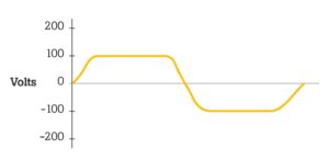
The Fluke 87 V provides True-RMS measurements that give correct but lower readings than mid-range instruments, such as the Fluke 27 II, on square waves or waveforms resembling square waves. Mike closed his Fluke 120B industrial ScopeMeter on and showed the voltage waveform. The display showed that the waveform was severely truncated at the top, making it look more like a square wave than a sine wave. The peak value measured only 135 V, instead of the expected 162 V.

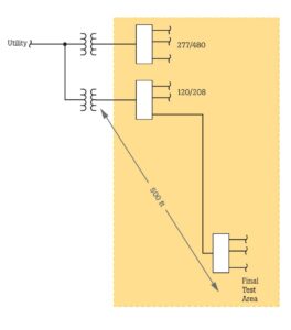
Mike drew a one-line diagram of the system. The one-line showed that the transformer supplying the test area was on the other side of the building, about 150 metres away. Most of the loads on that transformer were non-linear and reached high peak currents at the voltage peak. The combination of high peak currents and high impedance from the long distance combined to cause severe voltage drops at the end of the circuit, right at the location of the test area.

Theory and analysis

Since the internal circuits of the medical machine operated on a low DC voltage, the internal power supply would have a diode/capacitor input circuit that required a minimum peak voltage for proper functioning. The nameplate of the medical machine stated that the machine required a supply voltage between 100 and 135 V rms AC. The engineers who designed the machine and specified the nameplate assumed that the supply voltage would be a sine wave, so the minimum peak would be 141 V peak (100 x 1.41). Since the measured value of the peak voltage was only 135 V, the machine was running at a peak voltage that was already 6 V below the absolute minimum required. When the fan was switched on, the peak current energised by the fan motor reduced the voltage to a point where the machine's power supply was no longer normal. This caused the machine to reset itself.

Solution

The problem of voltage peak capping (flat topping) is common in high-tech buildings. Many of the buildings in use today are not designed to cope with the huge amount of computing and non-linear loads that are so common today.

In this case, it would be necessary to rewire everything thoroughly to reduce the voltage drop between the transformer and the load. An alternative would be to place the most sensitive loads closer to the transformer.

Read more
power consumption monitoring

5 reasons to monitor power consumption

power consumption monitoringThe ability to quantify energy consumption is essential for your plant and your team. Power consumption monitoring of your installation provides you with the data needed to make important energy management decisions.


Why monitor power consumption with a Power Logger?

  • Understanding the capacity of your existing electrical distributor
  • Troubleshooting circuit breaker tripping problems
  • Identifying energy costs
  • Tracking energy waste


Ask our experts for advice

1. Installation safety

Electricians often have to perform a load analysis before new loads can be added to an existing panel. Why? These requirements are set by the electrical inspector, the electrical engineer who designed the project or the customer adding the new loads. The purpose is to determine whether there is sufficient capacity to add new loads.

In a load analysis, a power logger used to document existing load levels (three-phase power dissipation) over long periods of time. And this is where safety comes into play. On the one hand, load analysis can be used to ensure compliance with local safety regulations. On the other hand, failure to conduct a load analysis before adding new loads may result in the overloading of an existing electrical source or the creation of unsafe and unreliable electrical situations.

2. Managing energy costs and realising savings opportunities

Energy costs are a large part of total operational costs, and yet many companies do not have a good overview of where their energy money is going. They only get an overall monthly bill, with no indication of whether that consumption is normal or excessive for that month's operations.

By logging energy consumption at the main service input and then at large loads and secondary feeds, facilities can gain insight into how much energy is consumed when, by what and at what hourly rate. The data will actually always show energy wastage that can be corrected by changes in operations. For example, consider switching off certain loads, reducing loads during periods of high tariffs, or adjusting the schedule so that loads are operational during periods of off-peak tariffs.


Schedule a consultation

3. Electricity bill accuracy

Owners of large and medium-sized facilities often install submeters so they can bill tenants for their specific electricity consumption. However, these submeters are usually installed incorrectly, resulting in unreliable data. Installation problems range from power inverters placed incorrectly and power inverters on the wrong phase, to errors in submeter configuration.

A good practice is to check the measured value with a portable energy logger. The logger data provides an order-of-magnitude comparison of what is charged with what is consumed. A significant difference between the energy consumption charged and the logger data indicates that the submeter setting should be investigated.

4. Rebates and financial incentives

Utilities offer premiums and rebates to encourage their customers to reduce their energy consumption. The aim is to serve more customers with the same current energy supply, as building new power plants is not an option. Many premiums and rebates are aimed at retrofitting existing buildings, with energy-efficient lighting and high-efficiency motors, for example, or replacing motor starters with frequency-controlled drives.

To grant the financial incentive bonus, the utility first requires proof of energy savings - and for this, a load analysis is ideal. A load analysis performed before a retrofit identifies the current energy consumption for reference, a load analysis after a retrofit confirms the energy savings achieved by the retrofit.

5. Detecting problems with mains power quality

Often, the only way to solve a problem is to record and analyse data over a long period of time. For these more complex problems, energy loggers are invaluable, and they are much more affordable and easier to use than a complicated Power Analyzer.

A good example is when a circuit breaker trips randomly. Obvious situations, such as a heavy motor starting, are not always the cause. In reality, the cause of the tripping may be something that does not seem obvious, or may only occur when technicians are not present to notice it (e.g. at night). Having a maintenance technician monitor the load until the circuit breaker trips is impractical. Connecting an energy logger to the load side of the circuit breaker to record the current draw for an extended period of time can then help to solve the problem.

Read more

Celebrate 75 years with FLUKE

For 75 years, Fluke has proudly served our test and measurement customers with premium products rooted in safety and reliability. To celebrate the occasion, Fluke is proud to announce the spring campaign, celebrating our 75th anniversary, featuring several best-selling items

Offer valid from 1 October 2023 to 31 December 2023

Download brochure
Read more
power supply quality

Detecting energy waste by managing grid power quality

power supply qualitySaving energy and minimising energy waste are important aspects of energy consumption. If you want to save energy, you need to identify your energy consumption and develop an energy saving plan for power quality management, regardless of the sector you work in.


Benchmarking electrical energy consumption

The first step in developing a power quality management programme is to benchmark your current electrical energy consumption in the plant. In doing so, look for quick and easy solutions, such as areas that are typically closed on weekends and can be switched off. Track areas that contribute to your energy consumption outside major assets, such as extra electric heating, lights that are still on and computers that are not switched off.

Once you have identified and implemented these quick wins, conduct more detailed analyses in the building or on campus. Perform load analyses on assets across the area with theFluke 1777 three-phase Power Quality Analyzer. These measurements may show where significant energy savings can be made, for example by switching off certain systems at night when they are not in use.

Advanced power quality considerations
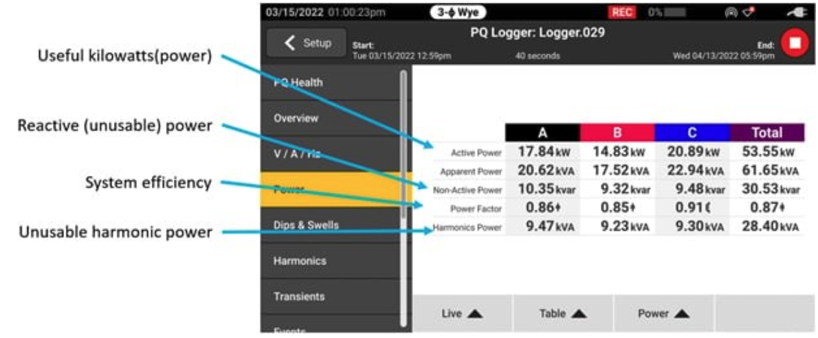
When power flows, some of the energy generated is inevitably lost in the form of heat.

The next step in reducing your energy consumption is to identify where energy wastage occurs. One area of concern is losses in conductors. When current flows through conductors, some of the energy generated is wasted as heat. If you want to solve this problem, apply the fundamental I2R equation indicating the current supplied. There are 2 possible solutions here: lower the current (I) for less kW or lower the resistance (R). Both create a problem:

  • At a lower current (I), the load does not operate correctly
  • Reducing resistance (R) may cost more, as copper or aluminium conductors need to be installed


So what is the best solution?

Consider the size of the conductor. In the National Electric Code (NFPA 70 or NEC 100) you will find a lot of advice on the size of a conductor and the ideal conductor size is described for almost all circumstances. The main consideration for the size of conductors is to ensure their safe operation with the most suitable insulation. The length, cross-sectional area and rated current expected to be required are decisive here. This will ensure minimal energy losses, typically 2% or less, and an acceptable voltage drop in the conductor. Another option is to install more efficient loads. Check whether the motors might be oversized for the current application.

Energy waste

These codes and guidelines are useful for new work, but once cabling is in place and loads are installed, the result is not always optimal. Over time, equipment can change due to additions, modifications, moves and age. This can have a major effect on energy waste. Key areas where energy waste can occur are related to your mains power quality: voltage regulation, harmonics, power factor and asymmetric loads.


Schedule a consultation

Voltage regulation

Voltage regulation aims to reduce energy consumption in loads that are voltage dependent. This is done by reducing or regulating voltage levels within the equipment manufacturer's specifications to yield energy savings. As more efficient loads are installed on a transformer, the voltage in the system may increase or be misregulated.

Use a Fluke 1777 Power Quality Analyzer to identify voltage regulation problems and detect transient voltages and voltage imbalances. Both problems can lead to failures, unplanned downtime and costly repairs.

power quality managementHarmonischen

Harmonics distort voltage and current so that the ideal sine wave for voltage is not maintained. One of the most well-known effects of harmonics in electrical systems is the excessive heat they cause in conductors. This results in overheating in phase and neutral conductors, known as ‘triple harmonics.’

The extra heat causes problems in wiring, motor windings and transformers. The overheating can cause significant damage or catastrophic failure, resulting in unscheduled downtime and expensive repairs. To measure and diagnose harmonics, use aFluke 1770 series three-phase Power Quality Analyzer.

Benefits of power quality analysis

If, after power quality analyses, it is visible where energy is being wasted, you can take steps to solve the problems:

  1. Perform preventive maintenance routinely so you can continue to measure against your benchmark and address problems as soon as they arise.
  2. Install harmonic filters on loads that increase the harmonic distortion of your installation.
  3. Address the causes of imbalance. This may mean setting up a repair or replacement schedule for large engines that have problems with mechanical imbalance.
  4. Limit problems caused by asymmetrical loads. In some cases, this may mean adjusting single-phase loads to distribute them more evenly between phases.
  5. Replace blown fuses if necessary. A blown fuse on a group of three-phase power factor upgrade capacitors may also be the cause of the problem; replacing the fuse may solve a major imbalance.

Mains power quality analyses show what can be done to save energy, reduce energy losses due to problems in an installation and reduce energy costs. Monitoring mains power quality can provide insight into the cause of problems and how to solve them.

Mains power quality analyses provide some other benefits besides energy savings:

  • Discovery vhan potential weaknesses in assets that could cause a major disruption
  • Discovery of equipment failures that could lead to worsening problems
  • Discovery of improperly installed circuit breakers prone to inadvertent tripping
Read more
compressed air, gas and vacuum leaks

This is how you detect compressed air, gas and vacuum leaks AND find hidden profits

Fluke Sonic air leak detectorFor industrial plants, compressed air, gas and vacuum systems are an essential source of converted energy. Compressors are simpler than other sources of energy such as electricity and they are everywhere in today's factories. They power machines, tools, robots, lasers, product handling systems and much more.

Yet many compressed air, gas and vacuum systems suffer from wear and poor maintenance, contributing to the biggest waste of all: ever-present leaks. These leaks may be hidden behind machinery or located at connection points, in fixed overhead lines or in cracked pipes or worn hoses. The waste increases rapidly and can even lead to downtime.


Ask our experts for advice

Detecting and fixing leaks is not easy

Many factories and plants do not have a leak detection programme. Detecting and fixing compressed air, gas and vacuum leaks is not easy. Quantifying the amount of waste and determining the cost requires energy specialists or consultants who use energy analysers and loggers to monitor your air systems. By systematically calculating the annual cost savings from fixing leaks, they can make a strong business case for undertaking such a project.

Energy audits of compressed air systems are often carried out through partnerships of industry, government and non-governmental organisations (NGOs). One such partnership is the Compressed Air Challenge (CAC), a voluntary collaboration between these groups. Its sole purpose is to provide product-neutral information and educational materials to help industries generate and use compressed air with maximum sustainable efficiency.

The high cost of wasted air

According to the U.S. Department of Energy, a 1/8″ (3 mm) leak in a compressed air line can cost more than $2,500 a year. The Department of Energy estimates that an average US plant that is not properly maintained can waste 20% of its total compressed air production capacity due to compressed air, gas and vacuum leaks. The New Zealand government, as part of its Target Sustainability project, estimates that system leaks can account for 30 to 50% of a compressed air system's capacity. Rapid detection of compressed air, gas and vacuum leaks is a key factor in finding hidden profits. Air leaks can also lead to capital expenditure, rework, downtime or quality problems and higher maintenance costs.

To compensate for pressure loss due to leaks, business managers often tend to overcompensate by purchasing a larger compressor than necessary, which incurs significant capital costs and higher energy costs. System leaks can also lead to air equipment failure due to low system pressure. This can lead to production delays, unplanned downtime, quality problems, shorter lifespan and increased maintenance due to unnecessary switching compressors on and off.

For example, the maintenance manager of a manufacturer in the US says that low pressure in one of their air tools can lead to defects in their products. “Incorrect torque, either too low torque or too high torque, can result in recalls. This also leads to more man-hours in something that should be a very standard process,” he says. “It is throwing money down the drain through loss of profits and loss of products. At worst, demand may also be at risk because we could not deliver.”

It is no wonder that utilities, industry and government see compressed air systems as a potential source of cost savings. Compressed air, gas and vacuum leaks lead to waste. Fixing such leaks can save the company manager money and prevent the utility from having to build additional capacity into the system.


Schedule a consultation

Why ultrasonic leak detection is inefficient

Unfortunately, the most common leak detection practices are rather primitive. An old-fashioned method is to listen for hissing sounds, which are almost impossible to hear in many environments, and spray soapy water on the area of the suspected leak, which is messy and could potentially be a slip hazard.
The current tool for detecting compressor leaks is a ultrasound detector, a portable electronic device that recognises high-frequency sounds related to air leaks. Typical ultrasonic detectors help find leaks, but their use is time-consuming and repair staff can usually only use them during scheduled downtime, while servicing other critical machinery may be a better use of time. These instruments also require the operator to be close to the equipment to find leaks, making the instruments difficult to use in hard-to-reach places such as ceilings or behind other equipment.

In addition to the time required to detect leaks with suds or ultrasonic detectors, there may be safety issues with these techniques related to finding leaks above or below equipment. Climbing ladders or crawling around equipment can be hazardous.

Pioneering for compressed air leak detection

What if there was a leak detection technology that could determine the exact location of a leak up to 50 metres away, in a noisy environment, without having to turn off equipment? Fluke has developed an industrial acoustic camera that does just that. Industrial maintenance managers call the Fluke ii900 Sonic Industrial Imager“Pioneering” for compressed air leak detection.

Capable of detecting a wider frequency range than traditional ultrasonic devices, this new acoustic industrial camera uses new SoundSight™ technology to provide enhanced visual scans of air leaks, just as thermal imaging cameras detect hotspots.

The ii900 features an acoustic array of small, super-sensitive microphones that detect both sonic and ultrasonic sound waves. The ii900 recognises a sound source at a potential leak location and then applies algorithms that interpret the sound as a leak. The results produce a SoundMap™ image, a colour map overlaid on top of the visible-light image, - showing exactly where the leak is. The results are displayed on the 7-inch LCD screen as a still image or real-time video. The ii900 can store up to 999 image files or 20 video files for documentation or compliance.

Large areas can be scanned quickly, detecting leaks much faster than other methods. Filtering can also be done by intensity and frequency ranges. A team at a large factory recently used two ii900 prototypes and detected 80 compressed air leaks in one day. The maintenance manager said that using traditional methods it would have taken weeks to find that number of leaks. By quickly detecting and fixing leaks, the crew also avoided potential downtime, which can cost an estimated $100,000 an hour in lost productivity at this plant.

Where to find leaks:

  • Links
  • Snakes
  • Tubes
  • Fittings
  • Threaded pipe connections
  • Shortcuts
  • FRLs (combinations of filter, regulator and lubricator)
  • Condensate traps
  • Valves
  • Flanges
  • Gaskets
  • Air supply boilers

How much air do you waste?

The first step in controlling leaks in compressed air, gas and vacuum systems is to estimate the leakage rate. Some leakage (less than 10%) is to be expected. Anything more is considered wastage. The first step is to determine your current leakage load so that you can use it as a benchmark against which to compare improvements.

The best method for estimating leakage load is based on your control system. If you have a system with start/stop control, simply start your compressor when there is no demand in the system - after working hours or shifts. Then measure a number of compressor cycles to determine the average time before the loaded system is unloaded. If there is no equipment in operation, the unloading of the system is due to leakage.

Leakage (%) = (T x 100) ÷ (T + t)T = load time (minutes), t = relief time (minutes)

To estimate the leakage load in systems with more complex control strategies, place a pressure gauge downstream of the volume (V, in cubic metres), including all secondary boilers, mains and pipes. If there is no demand in the system, except for leakage, bring the system to normal working pressure (P1, in psig). Select a second pressure (P2, about half the value of P1) and measure the time (T, in minutes) it takes the system to drop to P2.

Leakage (cfm free air) = [(V x ( P1 - P2) ÷ (T x 14.7)] x 1.25

The multiplier 1.25 corrects leakage to normal system pressure, taking into account lower leakage as system pressure decreases.

Efficiently fixing and repairing leaks can lead to significant cost savings for air-dependent businesses. Companies can not only save on energy consumption by repairing leaks, but can also improve production and extend the life of equipment.

Read more
Additel ADT793

Meet Additel's new pressure regulators, ADT773, ADT783 and ADT793.

Additel's new pressure controllers combine advanced control and measurement technology, modular design and user-friendly features in one powerful package. To achieve speed, control and accuracy in a wide range of applications, we have developed three different controller models: the ADT773 (LLP model, -0.95 to 1 bar), ADT783 (pneumatic model, -0.99 to 250 bar) and ADT793 (hydraulic model, 0 to 1000 bar). For users who want automated manufacturing, testing and calibration, our new pressure regulators can get the job done.

Read more
Fluke webinar

Fluke live webinar: Energy saving in industry

Thursday 22 June

One session at 10 a.m. and one at 1 p.m.

Optimising the consumption of electrical energy is a requirement today. With current energy price trends, perhaps as an additional incentive for companies. Not only for designers of new installations but also for owners of existing systems. ‘how do I make my installations operate as efficiently as possible with the lowest possible kWh consumption’. To determine efficiency, measurement is essential. ‘Measuring is still knowing’. The more parameters are measured, the more data there is to map energy flows, load profiles and efficiency. Potential improvements and corrections can be made after analysis.

A rewarding system in terms of energy savings is compressed air. With the compressor as the load and the application itself, this is so-called ‘low hanging fruit’ in terms of energy savings and efficiency increases. This example will also be taken into account to see how leaks can be efficiently identified and quantified.

This Webinar focuses on measuring the important parameters. To see, through some examples, how these can be measured and analysed.

In 45 minutes, we will review some test and measurement challenges with Fluke solutions. Test and measurement solutions that are ideal for measuring, collecting, analysing and reporting the desired parameter data.


Link for registration 10am webinar:

https://fluke-emea.zoom.us/webinar/register/6416847571656/WN_6RguJiR4SOqo6v-x12vOmw

Link for sign-up 1pm webinar:

https://fluke-emea.zoom.us/webinar/register/1116847578756/WN_dTA02swKRfyItnunvvESwg

Read more
Additel-762W-1

New!!! ADDITEL 762W!!!

The perfect solution for automatic calibrations without oil up to 700 bar!

The Additel 762W automatic pressure calibrator offers a revolutionary turnkey solution for automated pressure calibration up to 700 bar using deionised water as the working medium. Designed for use in both the field and laboratory.

We keep our customers in mind when designing our most capable pressure calibrator to date.

More info
Additel ADT762W Automatic pressure calibrator
Read more