 The case of medical device failures is a classic example of the importance of a systematic approach to troubleshooting mains power quality diagnostics. This is the story of Mike, an independent contractor working with a number of high-tech factories.
The problem
Mike met on site with a building manager who was frustrated with his electrical system. According to the manager, nothing that was electrical was working as it should in the building and no one had been able to identify how this could be or could provide a solution. The administrator further told Mike that three of his electricians had quit and that he was now in real trouble.
Mike asked questions to get a more detailed picture of the problem, but the feedback did not yield much useful information. Mike liked to always follow the motto ”When in doubt, look where the casualties are” and therefore asked to go to the part of the building where the problems were most severe.
Visual hints
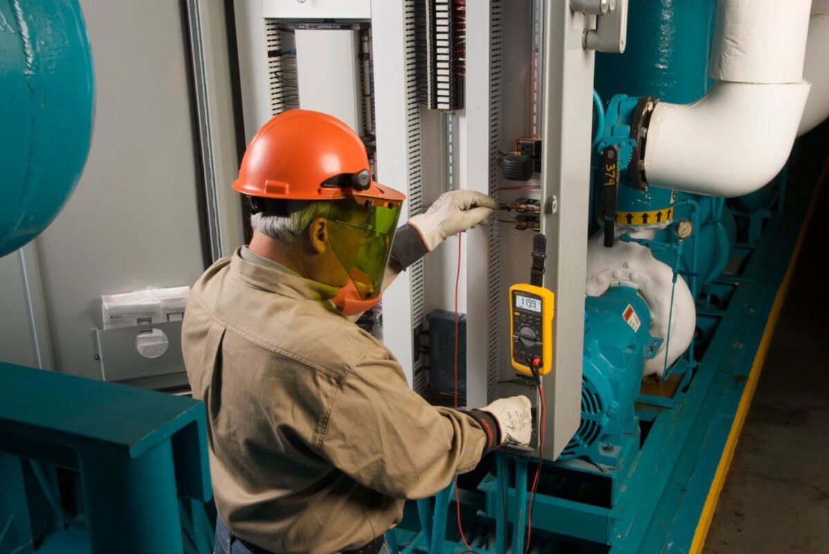
In one corner was a large medical machine performing a critical testing procedure. The machine was equipped with a large screen, keyboard and control panel with a number of cables and hoses leading to other pieces of equipment. The control screen displayed that the test procedure was ”In progress”.
Next to a machine was a workbench set up for repairing circuit boards. On the workbench was a soldering iron, an illuminated magnifying glass and a fan. The workbench's socket was plugged into the same socket as the large medical machine. Mike observed the person at the workbench extending his hand and turning on the fan. At that moment, the control screen on the medical machine went blank for a moment and then came back on with the words ”Programme reset” displayed in large letters.
 Measuring and evaluating
Mike measured the voltage at the socket that powered both loads. His Fluke 87 V industrial multimeter measured 115 V. The building manager repeated the measurement with his Fluke 27 II Rugged digital multimeter, which displayed 118 V. Why this difference?
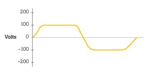
The Fluke 87 V provides True-RMS measurements that give correct but lower readings than mid-range instruments, such as the Fluke 27 II, on square waves or waveforms resembling square waves. Mike closed his Fluke 120B industrial ScopeMeter on and showed the voltage waveform. The display showed that the waveform was severely truncated at the top, making it look more like a square wave than a sine wave. The peak value measured only 135 V, instead of the expected 162 V.
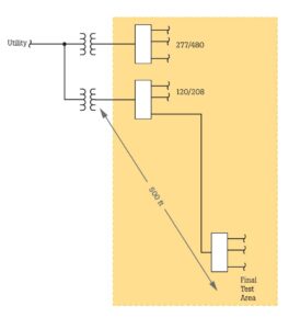
Mike drew a one-line diagram of the system. The one-line showed that the transformer supplying the test area was on the other side of the building, about 150 metres away. Most of the loads on that transformer were non-linear and reached high peak currents at the voltage peak. The combination of high peak currents and high impedance from the long distance combined to cause severe voltage drops at the end of the circuit, right at the location of the test area.
Theory and analysis
Since the internal circuits of the medical machine operated on a low DC voltage, the internal power supply would have a diode/capacitor input circuit that required a minimum peak voltage for proper functioning. The nameplate of the medical machine stated that the machine required a supply voltage between 100 and 135 V rms AC. The engineers who designed the machine and specified the nameplate assumed that the supply voltage would be a sine wave, so the minimum peak would be 141 V peak (100 x 1.41). Since the measured value of the peak voltage was only 135 V, the machine was running at a peak voltage that was already 6 V below the absolute minimum required. When the fan was switched on, the peak current energised by the fan motor reduced the voltage to a point where the machine's power supply was no longer normal. This caused the machine to reset itself.
Solution
The problem of voltage peak capping (flat topping) is common in high-tech buildings. Many of the buildings in use today are not designed to cope with the huge amount of computing and non-linear loads that are so common today.
In this case, it would be necessary to rewire everything thoroughly to reduce the voltage drop between the transformer and the load. An alternative would be to place the most sensitive loads closer to the transformer.