Blog

LHM Advanced Engineering

Advanced engineering

This year, you can find us at Advanced Engineering 2024 where you can discover our products and services and meet our team in person. You can find us at stand 3238.

Curious about the latest trends in calibration?

Then be sure to drop by our stand 3238! We will be happy to show you how our calibration services, both on-site and in our lab, make a difference. Our team of experts is ready to answer all your questions. Don't miss out and discover our calibration devices.

Read more
calibration additel

Automate, record, and eliminate errors. Automate and maximise efficiency!

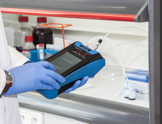
Calibration is a crucial process in various industries, essential for maintaining product quality, safety, and durability. Although regular calibration is a standard task, the importance of accurate documentation is often underestimated, mainly due to time constraints or the pressure of other daily tasks. In certain situations, documentation is performed manually, which is not only a time-intensive process but also increases the risk of human error during and after calibration.

Additel calibration

By using calibration tools with automatic documentation functions, you can address these challenges efficiently. These instruments automatically record all test results and provide instant pass/fail indication. Moreover, they enable you to transfer calibration data to calibration management software, reducing the risk of errors and improving the integrity of calibration results.

Benefits of an automatic documenting calibrator:

  • Time saving: Automatic storage of calibration results and execution of calibration procedures save valuable time.
  • Efficiency: Manual transfer of results is unnecessary, saving time and resources.
  • Accuracy: Reduces the risk of errors and increases the consistency and quality of calibration results.
  • Complete traceability: Provides a fully traceable calibration system for your entire organisation.

Discover the advantages of an automatic calibrator compared to the traditional calibration method:

Watch it in the following video:

Wondering which calibrator is right for you? Then ask our expert advice.

Read more

Pumps and Valves 2024

This year, you can find us at Pumps & Valves 2024 where you can discover our products and services and meet our team in person. Together with our sister company Schaefer Technology. You can find us at stand 4156.

Curious about the latest trends in calibration?

Then be sure to drop by our stand 4156! We will be happy to show you how our calibration services, both on-site and in our lab, make a difference. Our team of experts is ready to answer all your questions. Don't miss out and discover our calibration devices.

Collaboration LHM Instrumentation and Schaefer Technology

Schaefer-Tec is part of Aptco Group, a leading Belgium-based international technology group specialising in distribution. Schaefer-Tec has divisions in Germany, France, Switzerland and Romania. For more than 60 years,

Schaefer-Tec the official European distributor of Teledyne Hastings Instruments (USA): vacuum gauges, sensors, flow meters and controllers. The vacuum instruments use various technologies such as thermocouple, piezo and pirani sensors. The flow meters cover both low and high volume flows, corrosive gases and low dP requirements.

Teledyne Hastings Instruments is ISO 9001:2015 certified and manufactures a complete range of instruments that allow measurement and control of vacuum, pressure and gas flow.

Would you like to know more about this? Then contact product specialist: jan.vanmoerkerke@schaefer-tec.com

Read more
Fluke thermal cameras

10 things you need to know about thermal imaging cameras

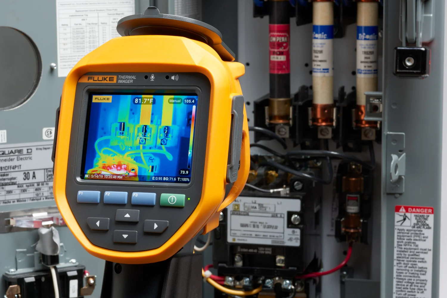
Whether you have a simple point-and-print model or a highly sophisticated thermal imaging camera with all possible options; you should consider the following features and specifications:

1. Resolution

    • Detector resolution is the number of detector pixels of the camera. More pixels means higher resolution.
    • Spatial resolution is based on the detector pixels and the FOV, combining them to define the image seen by the camera at a given time. Spatial resolution can be used to define the smallest detectable object size. Lower spatial resolution means more detail and higher image quality.
Fluke thermal imaging camera

2. Focus

When choosing a focusing mechanism, it is important to consider your skills and application. These are the most popular focusing systems:

    • Fixed: Just point and print
    • Manual: Precise step-by-step focusing
    • Auto focus: Automatically focuses on an object but may require manual adjustment.
    • Laser-controlled automatic focusing: Uses an integrated laser rangefinder to calculate the distance to the object.
    • Multifocal: captures multiple images of the object with different focus depths and uses software to combine them into a single image with an extremely sharp depth of field. At Fluke Corp. for example, this technology is called MultiSharp™ Focus.

3. Temperature range

The highest and lowest temperature you determine during your inspection determines the temperature range you need for your thermal imaging camera. You can select a camera with a wide temperature range that automatically determines the range based on your frame, or allow you to select the temperature range manually.

4. Lens options

With a camera with interchangeable lenses, you are more versatile, allowing you to inspect many more types of installations and situations. There are plenty of choices for numerous applications: standard, wide-angle, telephoto and macro.

5. Saving images and associated data

Save infrared images and digital images (sometimes with voice notes) to internal memory, a removable SD card or a USB stick. It is important to have the flexibility to save images and additional associated data to different media for backup or sharing.

6. Colour palettes

Subtle differences are more quickly noticed in a monochrome display such as greyscale or amber. High-contrast palettes make it easier to quickly identify obvious discrepancies. You can change the palette in the camera or in the software.

7. Colour arms

Use it to quickly mark areas outside normal temperature ranges.

8. Emissivity and reflected temperature

Surfaces with low emissivity, such as shiny metals, can reflect infrared energy from other objects and affect your image and measurement accuracy. So look for the option to adjust parameters when choosing a thermal imaging camera.

9. Spot marks

Highlight specific temperatures on your image to simultaneously compare temperatures of multiple points in the same image.

10. Battery type and lifetime

Look for a battery with useful features such as a charge status indicator. Nothing is worse than starting an inspection without knowing the battery status. Also consider battery life and fast-charging capacity.

Need help choosing the right model?

Read more
Fluke thermal imaging camera

Everything you need to know about thermography and thermal imaging cameras

A thermal imaging camera is an inspection tool that captures infrared energy - radiation emitted by an object - and creates an image. Thermal imaging cameras, also known as infrared cameras and thermographic cameras, are ideal for industrial inspection. Maintenance, leak detection and machine troubleshooting are all common applications. 

What is a thermal imaging camera used for? 

Thermal imaging cameras can be used for a wide range of applications: building inspection, security, electrical maintenance, firefighting, gas detection and more. Thermography is a particularly powerful testing method for use in situations where: 

  • Remote inspection essential for safety 
  • Damage or decay is expressed by temperature changes, as in three-phase wiring 
  • Test objects/subjects are invisible due to poor visibility 
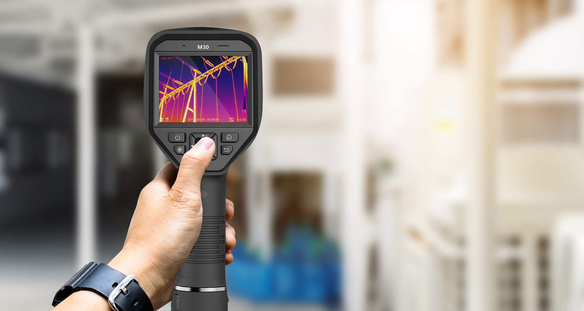
Hikmicro M30 thermal imaging camera

What is thermography? 

Thermography is the process of capturing infrared radiation and translating it into thermal images, or thermograms. Thermography shows variations in temperature expressed in colour. Powerful infrared cameras are incredibly sensitive and show heat in great detail with colour gradations. 

 Everything around us emits infrared energy - a heat signature. Thermography works by measuring infrared energy and converting that data into electronic images representing surface temperature. An optical system focuses infrared energy on a sensor array, or detector chip, with thousands of pixels in a grid. A matrix of colours corresponding to temperatures is sent as an image to the camera display. 

Read more

Expansion of ISO17025 scope to include tensile testing and temperature & 5-year extension

Last week, we received notification that the renewal of our BELAC accreditation 413-CAL for a period of 5 years has been approved.

BELAC is the Belgian Accreditation Body responsible for ISO 17025 accreditations in our country. ISO17025 is an internationally recognised standard that assesses the standards and technical competence of testing and calibration laboratories. In all words, it contains all the requirements that calibration laboratories must meet to demonstrate that they operate a quality system, are technically competent and can generate technically valid results.

Achieving this certification reflects our commitment to continuous improvement and demonstrates our commitment to accuracy and reliability of results. 

What does this mean for you?

It means you can continue to rely on the highest standards of accuracy, reliability and integrity in our services. Our continued compliance with the ISO17025 standard is the proof to provide you with the best service and results. 

You can here find our detailed scope.

Extension and expansion BELac LHM INstrumentation

In addition, the following changes were included in our scope:

  1. We are now able to pullbenches under BELAC to calibrate for a range of 100N to 300kN. This includes calibration in both tensile and pressure mode, allowing us to offer our customers a more versatile and comprehensive service.
  2. Thanks to the acquisition of the advanced Additel ADT850 calibration furnace, we can now temperature measurements perform up to 1200°C under BELAC accreditation, a significant increase from the previous limit of 300°C.
  3. Also for the calibration of low differential pressure gauges an extension was approved. Low-range sensors including 250Pa (2.5mbar) and 2500Pa (25mbar) can now be calibrated on-site and in our lab under accreditation.

If you have any questions about our calibration services, please do not hesitate to contact us at info@lhm-instrumentation.eu or 014 24 44 60. We are always ready to help and advise you.

Read more
Black Friday LHM Instrumentation

Black friday at LHM Instrumentation: 10% discount on all Additel equipment

From 20 to 30 November, LHM Instrumentation sets the standard for professional calibration instrumentation with an unmissable Black Friday offer. During this period, we are offering an exclusive discount of 10% on our entire range of Additel products.

Reliable precision with Additel
Additel is synonymous with precision and reliability, and we at LHM Instrumentation are proud to offer these top-quality tools that are essential for your professional work. With Additel's advanced technologies, you can significantly increase the accuracy and efficiency of your calibration processes.

Don't miss out: temporarily available
Remember, this special promotion is only valid from 20 to 30 November and cannot be combined with other discounts or promotions. It's time to take your instrumentation to the next level. Don't wait any longer as this promotion is temporary.

Claim your discount here
Read more
What is a diode

What is a diode?

What is a diode?

A diode is a semiconductor component that forms a kind of one-way switch for current. It allows current to flow easily in one direction, but hardly at all in the opposite direction.

Diodes are also called rectifiers called diodes, because they convert alternating current (AC) into pulsating direct current (DC). Diodes are classified according to type, voltage and current capacity.

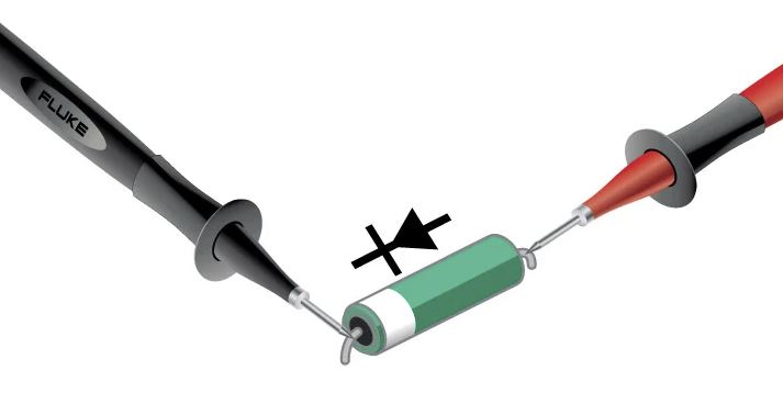
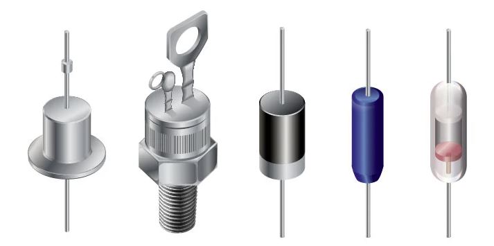
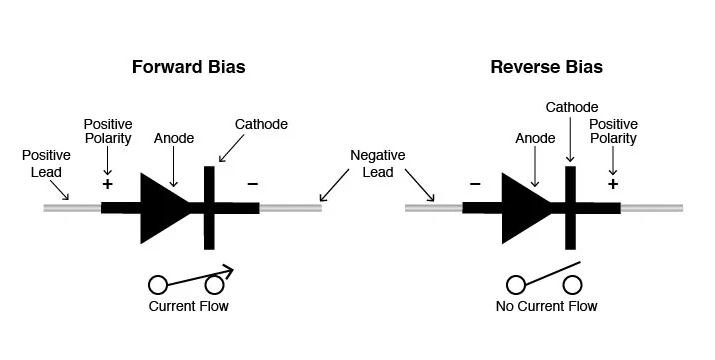
Diodes are polar: they have a anode (positive side) and a cathode (negative side). Most diodes allow current to flow only when positive voltage is applied to the anode. Different diode configurations are shown in this figure:

Diodes are available in different configurations. From left to right: metal housing, screw diode, plastic housing with band, plastic housing with chamfer, glass housing.

When a diode allows current passage, it is polarised in the forward direction. When a diode involves preload in the locking direction, it acts as an insulator and does not allow power passage.

Strange but true: The arrow of the diode symbol points in the opposite direction of electron emission. Reason: The symbol was devised by engineers and in their schematic representation, current flow proceeds from the positive (+) side of the voltage source to the negative (-). The same convention is applied for semiconductor symbols in which arrows are used: the arrow points in the ‘usual’ permitted direction of current flow, and against the permitted direction of electron flow.

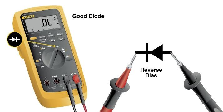
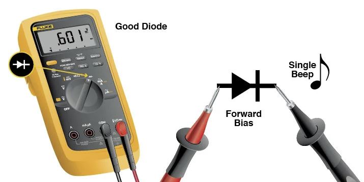
In a diode test of a digital multimeter, the diode produces a small voltage between the test wires, which is sufficiently strong to polarize a layer diode in the forward direction. The normal voltage drop is between 0.5 and 0.8 V. The resistance of a properly functioning diode in the forward direction is between 1000 ohms and 10 ohms if all goes well. When there is bias voltage in the reverse direction, the display of a digital multimeter the value OL is displayed (this indicates a very high resistance).

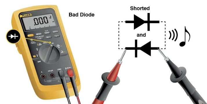
Diodes are rated for a specific current rating. If this is exceeded and the diode fails, a short circuit may occur and a) current may flow in both directions or b) current may be stopped in both directions.

Reference: Digital Multimeter Principles by Glen A. Mazur, American Technical Publishers.

Read more
What is the duty cycle?

What is the duty-cycle?

What is Duty-Cycle?

What is the duty cycle?

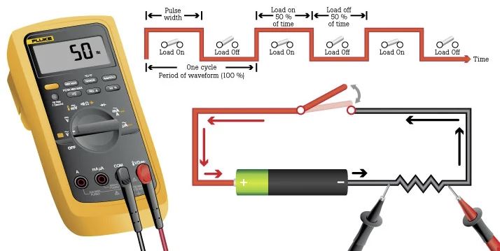
The duty cycle is the ratio of the duration that a load or circuit is ON to the duration during which the load or circuit is OFF.

The duty cycle, sometimes called ‘duty factor’, is expressed as a percentage of the ON time. A duty cycle of 60% indicates that a signal is ON 60% of the time and the remaining 40% OFF.

what is duty-cycle?


Many loads are quickly switched on and off via a fast-acting electronic switch that accurately manages the output power of the load. Load operation-such as the brightness of a lamp, the output of a heating element and the magnetic strength of a coil-can be controlled on a duty-cycle basis via periods of ON and OFF or cycles per second.


Duty-cycle simplified

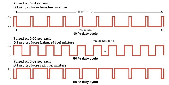
If the atomiser is pulsed ON with varying duration (this is called pulse width modulation), the duty cycle is always different. If the atomiser is pulsed ON for 0.05 second in a 0.1 second cycle, the duty cycle of the fuel atomiser is 50%. If the atomiser is pulsed ON for 0.09 second of the same 0.1 second cycle, the duty cycle of the fuel injector is 90%.


Example of duty-cycle

In a car electronic fuel injection system, voltage pulses fed to the fuel injection valve solenoid control the fuel injection valve at a fixed rate of 10 cycles per second or 10 Hz.

Pulse width modulation allows precise electronic control of the fuel supply to the motor. The average voltage for each duty cycle is determined by the amount of pulse time ON.

Duty-cycle controlled solenoid valves use a variable duty-cycle signal to vary the flow or adjust the pressure. The longer a solenoid valve stays open, the greater the flow and the lower the pressure built up. These solenoid valves are controlled by the power supply or ground.


What is pulse width?

Pulse width is a measure of the actual duty cycle in milliseconds. The time OFF does not affect the pulse width of the signal. The only value measured is how long the signal is ON (controlled by the ground).

Reference: Digital Multimeter Principles by Glen A. Mazur, American Technical Publishers.

Read more
What is Ohm's law?

What is Ohm's law?

What is Ohm's law?

The Ohm's law is a formula used to calculate the relationship between electric voltage, electric current and resistance in a circuit.

For people learning about electronics, Ohm's law, U = I x R, is as important as Einstein's theory of relativity (E = mc²) is for physicists.

U = I x R

Written out, this means voltage = current x resistance, or volt = amp x ohm or V = A x Ω.

Ohm's law, named after the German physicist Georg Ohm (1789-1854), relates to the most important quantities in circuits:

GreatnessSymbol for the way of OhmUnit of measurement (abbreviation)Role in circuitsIn case you were wondering:
TensionUVolt (V)Pressure activating the flow of electronsU = urgere (Latin for ‘to propel’)
CurrentIAmpere, amp (A)Speed of electron flowI = intensity
Resistance ROhm (Ω)Inhibits flowΩ = Greek letter omega

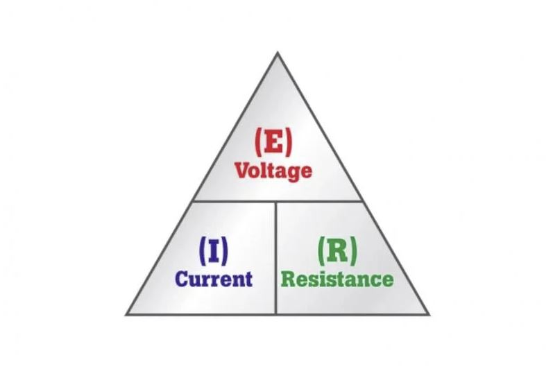
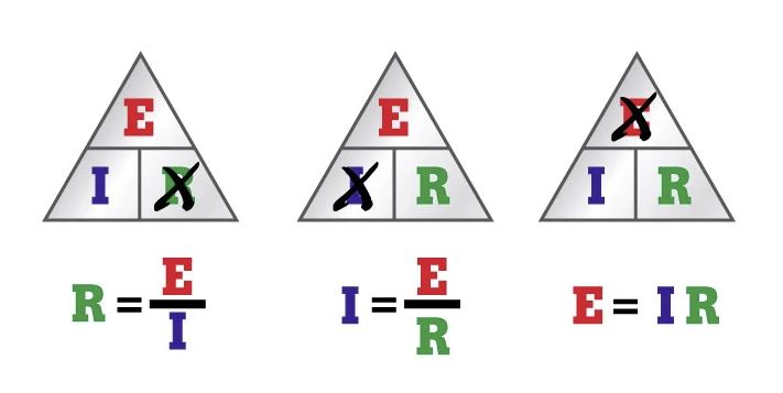
If two of these values are known, engineers can use Ohm's law to calculate the third. The pyramid can be changed as follows:
What is Ohm's law

If the voltage (E) and current (I) are known and you want to calculate the resistance (R), cross out the R in the pyramid and calculate the remaining equation (see the first pyramid, on the far left, above).

Remark: resistance cannot be measured when a circuit is in operation. Ohm's law is then especially useful if it needs to be calculated. It is not necessary to switch off the circuit to measure the resistance, because using the above variation on Ohm's law, a technician can calculate R.

If the voltage (E) and resistance (R) are known and you want the stream (I), cross out the I in the pyramid and calculate the remaining equation (see middle pyramid above).

If the current (I) and resistance (R) are known and you want the tension (E) calculation, multiply the two values at the bottom of the pyramid by each other (see the third pyramid, far right, above).

Try some example calculations for a simple serial circuit with one voltage source (battery) and resistor (bulb). In each example, two values are known. Use Ohm's law to calculate the third.

Example 1: Voltage (E) and resistance (R) are known.
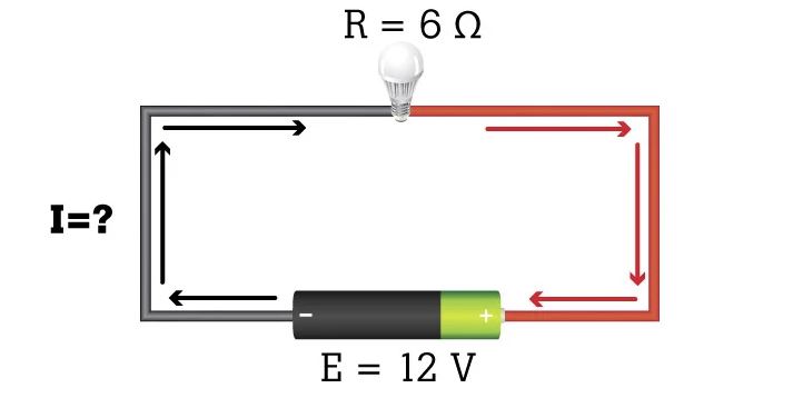
What is the current in the circuit?

I = U/R = 12 V/6 Ω = 2 A

Example 2: Voltage (E) and current (I) are known.
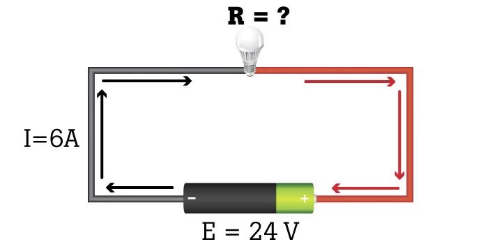
What is the resistance caused by the bulb?

R = E/I = 24 V/6 A = 4 Ω

Example 3: Current (I) and resistance (R) are known. What is the voltage?
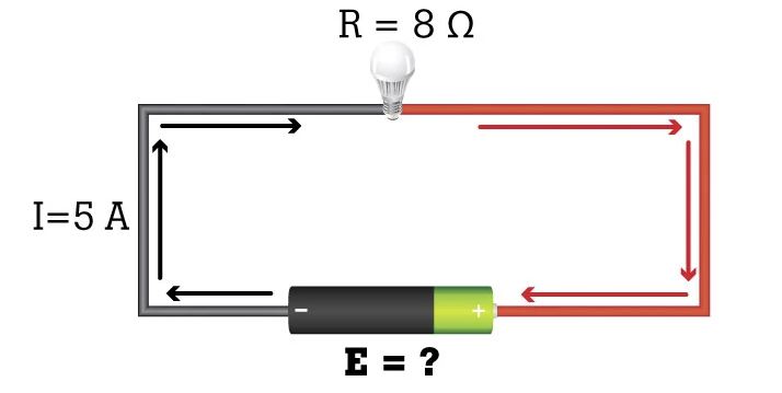
What is the voltage in the circuit?

E = I x R = (5 A)(8 Ω) = 40 V

When Ohm published his formula in 1827, his main conclusion was that the amount of electric current flowing through a conductor was directly proportional is with the voltage to which it is subjected. In other words, it takes one volt of pressure to push one ampere of current through one ohm of resistance.


What can be validated with Ohm's law

Ohm's law can be used to validate the static values of circuit components, current levels, voltage inputs and voltage drops. For example, if a measuring instrument observes a higher current reading than normal, it may mean that resistance has decreased or voltage has increased, causing a high-voltage situation. This may indicate a problem in the power supply or with the circuit.

In direct current (DC) circuits, a lower than normal current measurement value may mean that the voltage has decreased or the circuit resistance has increased. Possible causes for increased resistance are poor or loose connections, corrosion and/or damaged components.

Loads in a circuit take electrical current. Loads can be all kinds of components: small electrical appliances, computers, household appliances or a large motor. Most of these components (loads) have a rating plate or information sticker. This shows the safety certification and various reference numbers.

Technicians consult component nameplates to find out what the standard voltage and current values are. If, when measuring, a technician finds out that the digital multimeter or current clamp registers different values from the usual ones, he/she can use Ohm's law to determine which part of the circuit is not working properly and what could be causing it.


Basic knowledge about circuits.

Like everything else, circuits are made up of atoms. Atoms, in turn, are made up of subatomic particles:

  • Protons (with a positive electrical charge)
  • Neutrons (no charge)
  • Electrons (with a negative charge)

Atoms are held together by the forces of attraction between the nucleus of the atom and the electrons in the outer layer. When atoms in a circuit are exposed to voltage, they re-form and their parts exert an attraction potential known as a potential difference. Loose electrons with mutual attraction move towards protons, creating an electron flow (current). Any material in the circuit that interferes with this current is considered resistance.

Reference: Digital Multimeter Principles by Glen A. Mazur, American Technical Publishers.

Read more