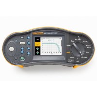
A solid, basic installation tester.
The Fluke 1662 offers you Fluke reliability, great ease of operation and all the testing capabilities you need for everyday plant testing.
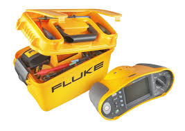
The Fluke 1662 puts more power in your hands by testing quickly and efficiently according to all local regulations.
Measuring functions
Other features
A solid, basic installation tester.
The Fluke 1662 offers you Fluke reliability, great ease of operation and all the testing capabilities you need for everyday plant testing.
| Alternating voltage measurement | ||
| Reach | 500 V | |
| Resolution | 0,1 V | |
| Accuracy 45 Hz - 66 Hz | 0,8% + 3 | |
| Input impedance | 360 kΩ | |
| Overload protection | 660 V RMS | |
| Passage test (RLO) | ||
| Measuring range (automatic range setting) | 20 Ω / 200 Ω / 2000 Ω | |
| Resolution | 0.01 Ω / 0.1 Ω / 1 Ω | |
| No-load voltage | >4 V | |
| Insulation resistance measurement (RISO) | ||
| Accuracy of test voltage (at rated test current) | +10%, -0% | |
| Test voltage | 100 V 250 V 500 V 1000 V |
|
| Insulation resistance range | 20 MΩ / 50 MΩ 20 MΩ / 100 MΩ 20 MΩ / 200 MΩ 20 MΩ / 200 MΩ / 500 MΩ 20 MΩ / 200 MΩ / 1000 MΩ |
|
| Resolution | 0.01 MΩ / 0.1 MΩ 0.01 MΩ / 0.1 MΩ 0.01 MΩ / 0.1 MΩ 0.01 MΩ / 0.1 MΩ / 1 MΩ 0.01 MΩ / 0.1 MΩ / 1 MΩ |
|
| Test current | 1 mA at 50 kΩ 1 mA at 100 kΩ 1 mA at 250 kΩ 1 mA at 500 kΩ 1 mA at 1 MΩ |
|
| Loop and grid impedance (ZI) | ||
| Reach | 10 Ω / 0.001 Ω / high-current MΩ mode | |
| Resolution | 0.01 Ω / 0.1 Ω / 1 Ω | |
| Expected earth fault current, PSC test | ||
| Reach | 1000 A / 10 kA (50 kA) | |
| Resolution | 1 A / 0.1 kA | |
| Calculation | Expected ground fault current (PEFC) or expected short circuit current (PSC) is determined by dividing the measured mains voltage by the measured loop resistance (L-PE) or mains resistance (L-N), respectively. | |
| Testing of earth leakage circuit breakers, tested types of earth leakage circuit breakers | ||
| Type of earth leakage switch | A =”4″, AC¹, G², S³ | |
| Comments | Reacts to AC ²General, no delay ³Time delay =”4″Responds to impulse signal =”5″Responds to flat DC signal |
|
| Switch-off time test (ΔT) | ||
| Power settings¹ | 10-30-100-300-500-1000 mA - VAR 10-30-100 mA |
|
| Factor | x ½, x 1 x 5 |
|
| Measuring range | Type G earth leakage switches | 310 ms 50 ms |
| Earth leakage switches type S | 510 ms 160 ms |
|
| Comments | ¹1000 mA only type AC 700 mA maximum type A in VAR mode VAR mode not available for type B. |
|
| RCD/FI tripping current measurement/rise test (IΔN) | ||
| Current range | 30% to 110% of rated current of RCCB¹ | |
| Step size | 10% of IΔN² | |
| Step time | Type G | 300 m/step |
| Type S | 500 m/step | |
| Measuring accuracy | ±5% | |
| Specified trip current ranges (EN 61008-1) | 50% to 100% for type AC 35% to 140% for type A (>10 mA) 35% to 200% for type A (≤10 mA) 50% to 200% for type B ²5% for type B |
|
| Comments | ¹30% to 150% for type A IΔN > 10 mA 30% to 210% for type A IΔN = 10 mA 20% to 210% for type B |
|
| Indication of phase sequence | ||
| Icon | Phase sequence indicator is active. | |
| General specifications | ||
| Dimensions (L x W x H) | 10 x 25 x 12.5 cm | |
| Weight (incl. batteries) | 1.3 kg | |
| Number and size of batteries | 6 AA batteries. | |
| Seal | IP-40 | |
| Safety | Complies with EN61010-1 ed. 2.0 (2001-02), UL61010, ANSI/ISA -s82.02.01 2000 and CAN/CSA c22.2 no. 1010 2nd ed. | |
| Overvoltage | CAT III / 500 V; CAT IV 300 V | |
| Performance | EN61557-1 to EN61557-7 2nd edition and EN61557-10 2nd edition | |

Select at least 2 products
to compare