FLUKE 190-Series III Scopemeter

Features
  • Specified for industrial environments: CAT III 1000 V/CAT IV 600 V
  • Automatically capture, view and analyse complex waveforms
  • Large, bright colour display for good on-site viewing
  • Download via USB and Wi-Fi for analysing data with FlukeView® software
  • Up to four independently floating isolated inputs, up to 1000 V
Categories: ,

High-performance portable oscilloscopes designed for demanding environments

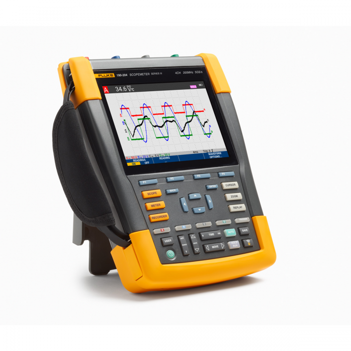
Designed to go anywhere, Fluke 190 Series III ScopeMeter® test tools are suitable for virtually any kind of on-the-go troubleshooting. These CAT III 1000 V/CAT IV 600 V test tools combine rugged portability with the high performance of table oscilloscopes to help you meet the challenges of installing, commissioning and maintaining industrial machinery, automation, process control and power electronics - from DC to 500 MHz - with ease.

Choose from two- or four-channel models and a range of bandwidths. High sampling rates of up to 5.0 GS/s, a resolution of 200 ps and deep memory with 10,000 samples per channel ensure that waveform details, noise and other disturbances are recorded and displayed with extreme accuracy. You can perform timing or amplitude measurements on three-phase or three-axis control systems, or simply compare and contrast multiple measurement points in a circuit under test. Features such as TrendPlot™ paperless recorder, ScopeRecord™ mode, Connect-and-View™ trigger function and a unique 100-screen Replay function help you diagnose problems quickly to minimise repair costs and downtime. Thanks to these features, the oscilloscopes are easy to use. Especially for analysing the most difficult problems, such as complex waveforms, induced noise, intermittent events and signal fluctuations or drift.

  • Up to four independently floating isolated inputs, up to 1000 V
  • Up to 5 GS/s real-time sampling (depending on model and channels used)
  • Deep memory: 10,000 points per scope line of the recorded waveform (Scope mode)
  • Safety specification CAT III 1000 V/CAT IV 600 V for industrial environments
  • Up to seven hours of battery operation with BP291
  • The large, bright colour screen is easily visible in almost any environment
  • Easy to store and display historical data and transfer to a PC via USB or WiFi
  • Easily accessible battery cover for quick on-site battery changes
  • Protection class IP51, dust- and drip-proof
  • Intelligent and automatic Connect-and-View trigger function for fast, slow and even complex signals
  • Frequency spectrum by FFT analysis
  • Automatic recording and reproduction of 100 screens
  • ScopeRecord mode provides 30,000 measurement points per input channel, for analysing low-frequency signals
  • TrendPlot paperless recorder with deep memory for automatic long-term measurements
  • DMM with a resolution of 5,000 counts in the 2-channel models
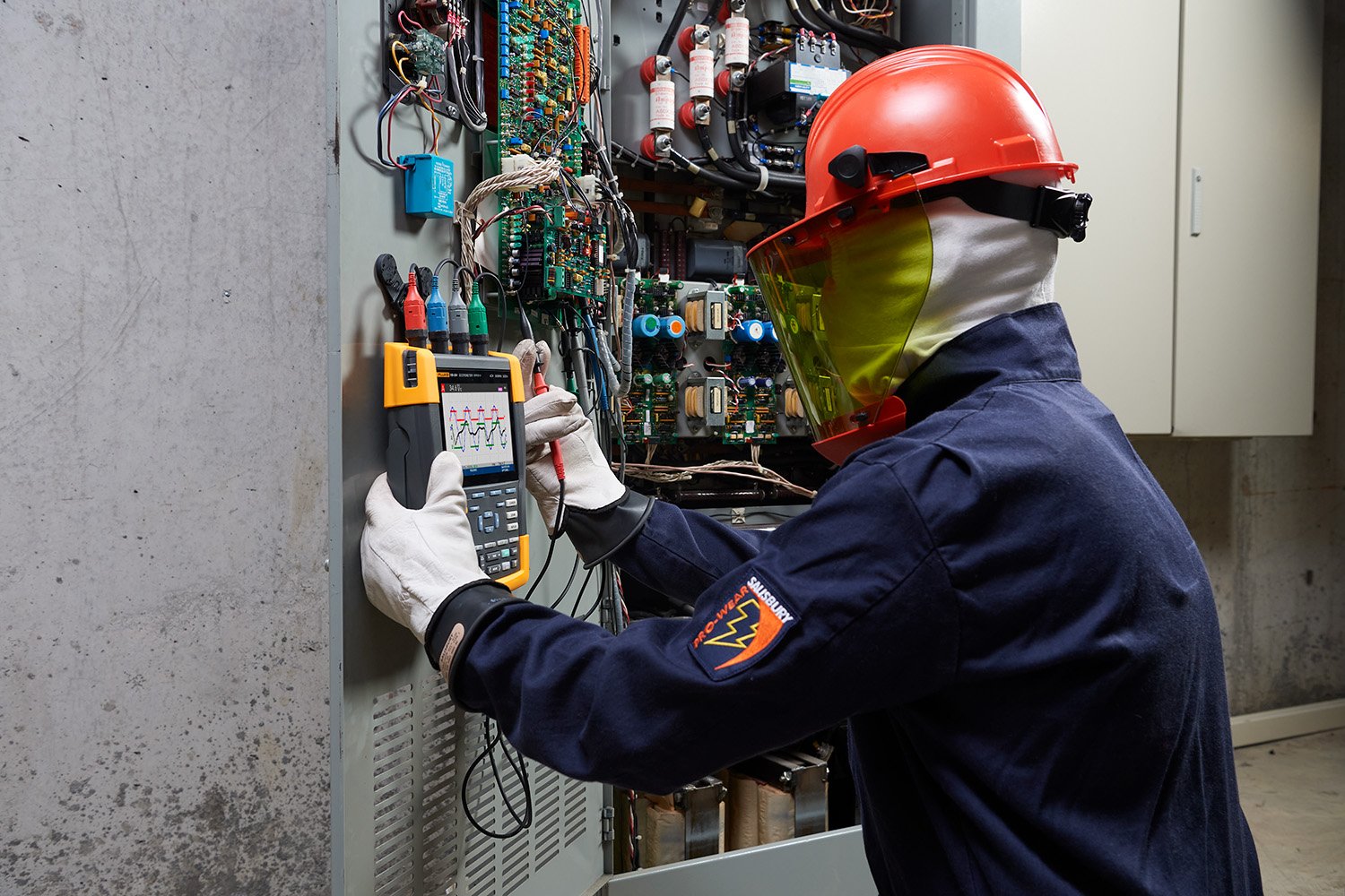
Safe measurement from mV to kV

Independently isolated inputs allow you to make measurements in mixed circuits with different earth references, reducing the risk of unwanted earth faults. Conventional tabletop oscilloscopes without dedicated differential probes and isolation transformers can only make measurements relative to mains supply earth. ScopeMeter 190 Series III test instruments are made to cover a wide application range from mV to kV. So you are equipped for everything between microelectronics and heavy-duty high-voltage electrical applications. Configurations of the 190 Series III, 60 MHz and 100 MHz include VPS421 100:1 probes for higher voltage applications, while the 200 MHz and 500 MHz configurations include VPS410-II 10:1 probes suitable for both microelectronics and higher voltage applications.

Protection class IP-51 for use in harsh environments

ScopeMeter portable test instruments are rugged, shockproof and designed for dirty, hazardous environments. Thanks to its sealed housing, the instrument is resistant to dust, dripping water, humid environments and airborne contaminants. You can rest assured that the ScopeMeter test instrument is always reliable, will do its job wherever you are.

USB and WiFi connectivity

The Fluke 190 Series III has two USB ports, electrically isolated from meetingang circuits, so you can quickly and easily transfer data to a PC, archive waveforms and share them with OEMs, colleagues and support staff. Or save waveforms, screenshots and instrument settings to USB memory devices for later use. Easily transfer stored files via a USB stick, direct connection via the USB connector or optional WiFi connectivity. These files can be used for further data processing or in FlukeView-2 software to study waveforms in more detail.

Connect-and-View-triggering

Connect-and-View triggering provides an instant, stable display without having to adjust settings. If you have used other oscilloscopes before, you know how tricky triggering can be. If the settings are incorrect, the results may be unstable or incorrect. Connect-and-View automatically ensures correct triggering by recognising signal patterns. Without even having to press any buttons, you get a stable and reproducible display of almost any signal, including motor drive and control signals. This feature is especially quick and convenient when you want to test multiple measurement points in quick succession.

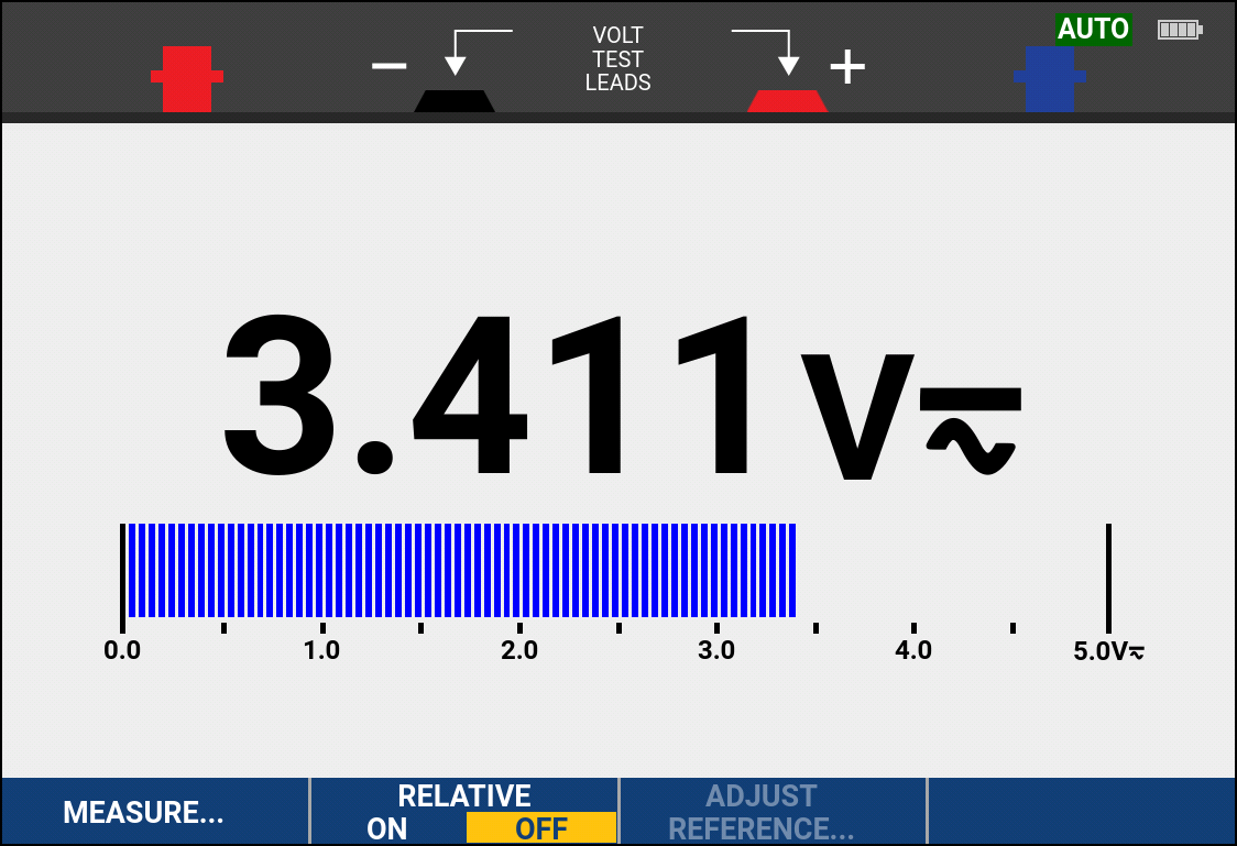
Connect-And-View captures even the most complex signals without additional settings
Built-in multimeter for convenient precision measurements

Built-in digital multimeter

Conveniently switch from waveform analysis to accurate multimeter measurements with the built-in 5000-count digital multimeter on two-channel 190 Series III models. Measurement functions include V DC, V AC, V AC+DC and resistance measurement as well as dial-through and diode test. Measurement of current and temperature using a suitable shunt, probe or adapter with a wide range of scale factors.

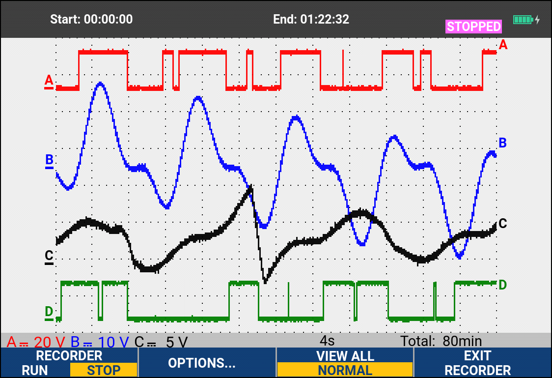
ScopeRecord™ mode for recording high-resolution waveforms

The ScopeRecord™ memory stores up to 30,000 or more data points per channel and records fast intermittent events or glitches with a duration of only 8 ns. (Two sets of multi-channel recordings can be stored on the internal memory for later analysis).

  • Stores certain events, such as start-up cycles of UPS systems, mains supplies or motors
  • In Stop-on-Trigger mode, the ScopeMeter test instrument automatically recognises a power failure and stores the data of the preceding waveform
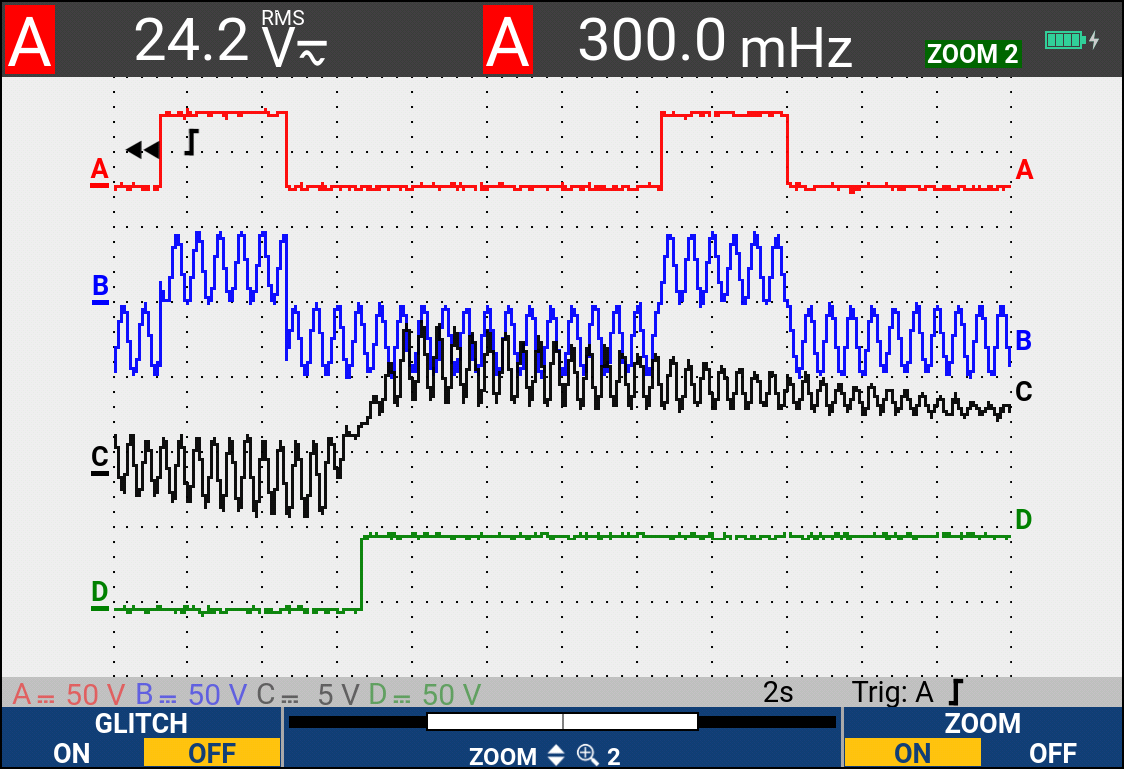
Record high-resolution waveform details over an extended period of time with ScopeRecord™ mode
Record the trend of multiple measurements, capturing intermittent signal events, signal drift or fluctuations

TrendPlot paperless recorder: records for up to 11 days, allowing you to detect intermittent faults

The hardest to find faults are the ones that occur only occasionally. These intermittent events can be caused by poor connections, dust, dirt and corrosion, as well as a wire or connector break. Mains power failures, fluctuations and interruptions, or starting or stopping a motor can also be to blame for a machine stopping. You may not be around when it happens, but your Fluke 190 Series II ScopeMeter measuring instruments will definitely not miss this event.

  • Minimum and maximum peak and mean values over time
  • Recording of any combination of up to four readouts including voltage, current, resistance, frequency, temperature and phase for all inputs, including time and date indication to track faults

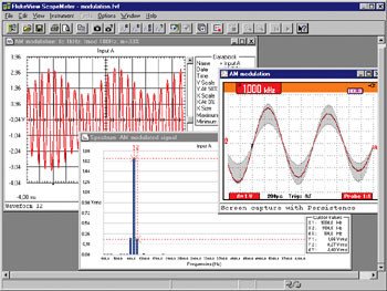
FlukeView™ 2 ScopeMeter software for documentation, archiving and analysis

Get more out of your ScopeMeter test instrument with FlukeView 2 ScopeMeter software for Windows.

  • Documentation: transfer waveforms, screenshots and data to your PC for printing or importing into a report
  • Add text to ScopeMeter test instrument settings: support technicians in retrieving settings
  • Archive: create a library of waveforms for easy reference or comparison of waveforms
  • Analysis: use cursors or export data to another analysis programme
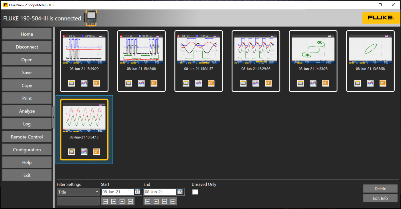
FlukeView-2 ScopeMeter software

Specifications: Fluke 190 Series III ScopeMeter® test instruments

Oscilloscope modes
190-062 190-102 190-202 190-502 190-104 190-204 190-504
Vertical rash
Number of channels 2 2 2 2 4 4 4
Bandwidth 60 MHz 100 MHz 200 MHz 500 MHz 100 MHz 200 MHz 500 MHz
Rise time 5.8 ns 3.5 ns 1.7 ns 0.7 ns 3.5 ns 1.7 ns 0.7 ns
Number of oscilloscope inputs 2 input channels plus external trigger 4 input channels
Channel architecture All inputs are completely isolated from each other and from earth. Inputs can be activated in any combination.
Input connector AC or DC, with earth level indicator
Input sensitivity With 10:1 probe, 20 mV to 1000 V/div
with 100:1 probe, 200 mV to 10 kV/div
Direct (1:1), 2 mV to 100 V/div
Bandwidth limitation 20 MHz and 10 kHz
Polarity Normal, inverse, variable
Input voltage Specification CAT III 1000 V/CAT IV 600 V, see general specifications for further details
Vertical resolution 8-bit
Accuracy 4 s to 10 µs/div 5 mV/div to 100 V/div, ±(1.5% + 6 counts)
2 mV/div, ±(1.5% + 10 counts)
Input impedance 1 MΩ (± 1%) // 15 pF (± 2.25 pF)
Horizontal
Maximum real-time sample rate (simultaneous sampling) 625 MS/s
(each channel)
1.25 GS/s (each channel) 2.5 GS/s (each channel) 5 GS/s (single channel) or
2.5 GS/s (dual channel)
1.25 GS/s (each channel) 2.5 GS/s (2 can)
1.25 GS/s (4 can)
5 GS/s (single channel) or 2.5 GS/s (2 can.) or 1.25 GS/s (4 can.)
Registration length Up to 10,000 samples per channel
Time base range 10 ns/div
up to 4 s/div
5 ns/div
up to 4 s/div
2 ns/div
up to 4 s/div
1 ns/div
up to 4 s/div
5 ns/div
up to 4 s/div
2 ns/div
up to 4 s/div
1 ns/div
up to 4 s/div
Time base in an order of 1-2-4
Slower time/division settings when using ScopeRecord™ roll mode (see ‘Recording mode’)
Maximum registration length 10,000 samples per channel in oscilloscope mode
30,000 points per channel in ScopeRecord™ roll mode (see ‘Registration mode’)
Timing accuracy ± (0.01% of reading + 1 pixel)
Registering glitches 8 ns (10 µs/div to 2 min/div)
Display and acquisition
Display 133 mm x 90 mm (5.3 inch x 3.5 inch) colour LCD display with high brightness
Display modes Any combination of channels; means on/off; reproduction.
Width of visible screen 12 divisions horizontally in oscilloscope mode
Digital Persistence modes Off, short, medium, long, infinity and envelope mode
Waveform calculation functions One (190-xx2) or two (190-x04) mathematical operations on 2 input channels (A and B, C and D): addition, subtraction, multiplication; X-Y mode; frequency spectrum with FFT
Acquisition modes Normal, average, automatic, single shot, ScopeRecord™ roll mode, capture voltage spikes, compare waveforms with automatic ‘pass/fail test’; reproduce
Triggering and delay
Source Input A, B or external (via meter input) Input A, B, C or D
Modi Automatic, Edge, Pulse width, N-cycle, External (190-xx2)
Connect-and-View™ Advanced automatic triggering that recognises signal patterns and automatically sets and continuously adjusts the triggering, time base and amplitude. This feature automatically displays stable waveforms of complex and dynamic signals, such as motor drive and control signals. Can be disabled if desired.
Pulse width triggering (on channel A) Pulse width as a function of time
allows triggering at t, =t, ≠ t, where t can be selected in steps of at least 0.01 div or 50 ns
Time delay 1 full screen at pre-trigger display or up to 100 screens (=1,200 divisions) at post-trigger delay
Double flank triggering Triggers on both rising and falling flanks
N-cycle-triggering Triggers on the Nth occurrence of a trigger event; N can be set in the range of 2 to 99
Automatic registration of 100 screens
In oscilloscope mode, the instrument ALWAYS remembers the last 100 screens - no specific setting by the user required. If an anomaly is detected, the REPLAY key can be pressed to repeatedly revisit the entire sequence of events on the screen. The instrument can be set to trigger on glitches (‘glitches’) or intermittent anomalies and operates in ‘babysit’ mode where 100 specified events are recorded.
Replay mode Manual or continuous reproduction of screens. Display of registered 100 screens as a ‘live’ animation or manually controlled. Each screen has a date and time stamp.
Storage of screens to be reproduced Ten sets of 100 screens each can be stored internally for later recall and analysis. Direct storage of additional sets on external flash memory drive via USB host port.
FFT - frequency spectrum analysis
Shows the frequency content of the waveform when using fast Fourier transform
Window Automatic, hamming, hanning or none
Automatic window Samples an acquired waveform again for optimal frequency resolution in the FFT resultant.
Vertical scale Linear/logarithmic (in volts or amps)
Frequency axis The frequency range is automatically set as a function of the time base range of the oscilloscope
Comparison of waveforms and pass/fail tests
Comparison of waveforms Provides storage and display of a reference waveform for visual comparison with newly acquired waveforms. The reference is derived from an acquired waveform and can be adjusted in the oscilloscope.
Pass/fail tests In waveform comparison mode, the oscilloscope can be set to store only matching (‘pass’) or only non-matching (‘fail’) waveforms obtained in the memory bank for displays to be reproduced for further analysis.
Automatic oscilloscope measurements
V DC, V AC RMS, V AC+DC, V peak max, V peak min, V peak to peak, A AC, A DC, A AC+DC, frequency (in Hz), rise time (when using cursors), fall time (when using cursors), power factor (PF), watts, VA, VA blind, phase (between any 2 inputs), pulse width (pos./neg.), duty cycle (pos./neg.), temperature in °C, temperature in °F (not for Japan), dBV, dBm in 50 Ω and 600 Ω, VVPWM AC and VVPWM(AC+DC) for measurement on pulse width modulated motor drives and frequency inverters, ratio V/Hz;
Advanced functions for power supplies and motor drives Ratio V/Hz, power factor (PF), watts, VA, VA blind, VPWMAC and VPWM (AC+DC) for measurement on pulse width modulated motor drives and frequency inverters
Course measurements
Source On any input waveform or on mathematically resulting waveform (excluding X-Y mode)
Two horizontal lines Voltage at cursor 1 and at cursor 2, voltage between cursors
Two vertical lines Time between cursors, 1/T between cursors (in Hz), voltage between markers, rise time with markers, fall time with markers; V RMS between cursors, watts between cursors.
Single vertical line Minimum, maximum -and average voltage at the cursor position; frequency and RMS value of individual frequency component in the FFT resultant
Advanced features mA*s (current as a function of time, between cursors); V*s (voltage as a function of time, between cursors); W*s (energy, between cursors)
ZOOM From a full registration overview to zoom in at sample level, at any registration length.
Meter modes
190-062 190-102 190-202 190-502 190-104 190-204 190-504
Meter inputs Via 4 mm banana connectors, fully isolated from oscilloscope inputs and oscilloscope ground Via BNC oscilloscope inputs
Number of measurement values One at a time via the DMM input Up to 4 automatic oscilloscope measurements simultaneously
Maximum resolution 5,000 counts ± 999 counts
(frequency: 9999 counts)
Input impedance 1 MΩ (± 1 %) // 14 pF (± 1.5 pF) 1 MΩ (± 1 %) // 15 pF (± 2.25 pF)
Advanced meter functions Automatic and manual range setting, relative measurements (zero reference), TrendPlot™ recording
The specified accuracy applies over the temperature range of 18 °C to 28 °C Add 10% of the specified accuracy for each degree C below 18 °C or above 28 °C
Tension
Accuracy V DC ± (0.5% + 6 counts) ± (1.5 % + 6 counts)
Accuracy V AC True RMS
15 Hz to 60 Hz ± (1 % + 10 counts) ± (1.5 % + 10 counts)
60 Hz to 1 kHz ± (2.5 % + 15 counts)
60 Hz to 20 kHz ± (2.5 % + 15 counts)
Accuracy V AC+DC True RMS
15 Hz to 60 Hz ± (1 % + 10 counts) ± (1.5 % + 10 counts)
60 Hz to 1 kHz ± (2.5% + 15 counts)
60 Hz to 20 kHz ± (2.5 % + 15 counts)
Voltmeter ranges 500 mV, 5 V, 50 V, 500 V, 1,100 V
Resistance
Reach 500 Ω, 5 kΩ, 50 kΩ, 500 kΩ, 5 MΩ, 30 MΩ
Accuracy ± (0.6 % + 6 counts)
Other meter functions
Continuity Beeper on < 50 Ω (± 30 Ω)
Diode test Up to 2.8 V
Current (A) A DC, A AC, A AC+DC when using an optional current clamp or shunt Scale factors: 0.1 mV/A, 1 mV/A up to 100 V/A and 400 mV/A
Temperature With optional accessories. Scale factors 1mV/°C or 1mV/°F
Registration mode
190-062 190-102 190-202 190-502 190-104 190-204 190-504
ScopeRecord™ rolling mode
Mode for storing waveforms from two or more inputs, using deep memory
Source and display Input A, input B, double
All channels are sampled simultaneously
Any combination of inputs, up to 4 channels.
All channels sampled simultaneously
Memory depth 30,000 data points, each with min/max information pairs
Min/max values Min/max values are generated at samples measured at high sample rates which ensures capture and display of voltage peaks.
Registration modes Single sweep (single scan), continuous rolling, Start-on-Trigger (via external trigger), Stop-on-Trigger (via external trigger) Single sweep (single scan), continuous rolling, Start-on-Trigger (via any channel), Stop-on-Trigger (via any channel)
Stop-on-trigger ScopeRecord mode can be stopped by a separate trigger event, or by an interruption
of a repeating trigger signal, via any input channel (via external trigger on the 190-XX2 series)
Horizontal scale Time from start and time of day
Zoom From a full registration overview to zooming in on sample level
Memory Two ScopeRecord waveforms with multiple inputs can be stored internally for later recall and analysis.
Sample rate and recording time range in ScopeRecord™ roll mode
Time base range 4 ms/div to 2 min/div
Registration time range 4.8 sec to 40 h
Time/division in ‘Show all’ mode’ 0.4 s/div to 4 h/div
Registering glitches 8 ns
Sample rate 125 MS/s
Resolution 160 μsec ~ 4.8 sec
TrendPlot™ registration
Electronic, paperless multi-channel recorder. Graphically plots, displays on screen and stores up to four automatic oscilloscope measurements or a DMM reading over time.
Source and display Any combination of oscilloscope measurements on any input channels, or DMM readout (instruments with 2 channels)
Memory depth 19,200 points (sets) per registration. Each recorded sample point contains a minimum, a maximum and an average value, plus a date and time stamp.
Reach Normal display: 5 s/div to 30 min/div; In show all mode: 5 min/div to 48 h/div (overview of total recording)
Registration time range Maximum 22 days, with a resolution of 102 seconds; maximum 5.5 days for 4 readouts.
Registration mode Continuous recording, starting at 5 s/div with automatic compression of recording
Measurement speed Three automatic measurements per second or more
Horizontal scale Time from start and time of day
Zoom Up to 64x zoom out for full registration overview, up to 10x zoom in for maximum detail
Memory Two TrendPlot records with multiple inputs can be stored internally for later recall and analysis.
Cursor measurements-all recording modes
Source Each scope line of a waveform in any waveform display mode (Scope, ScopeRecord or TrendPlot)
Two vertical lines Cursors can be used to identify the minimum, maximum or average value of any data point in a record, with time between cursors, time from start or absolute time.
General specifications
190-062 190-102 190-202 190-502 190-104 190-204 190-504
Input voltage range
Nominal maximum suspended voltage CAT III 1000 V/CAT IV 600 V (maximum voltage between any contact and the earth voltage level)
Input voltage measuring probe VPS410-II CAT III 1000 V/CAT IV 600 V (maximum voltage between standard 10:1 probe and reference lead)
Input voltage measuring probe VPS421 CAT III 1000 V / CAT IV 600 V (maximum voltage between probe point or reference lead to GND, 2000 V max between probe point and reference lead)
Maximum BNC input voltage CAT IV 300 V (maximum voltage directly at the BNC input)
Maximum voltage on meter input CAT III 1000 V/CAT IV 600 V
(safety banana plugs)
Store in memory and recall
Memory locations (internal) 30 waveform memories plus 10 registration memories plus 9 screenshot memories
30 waveform memories Each memory can hold up to 2 or 4 waveforms with their corresponding settings.
10 registration memories Each can consist of: a Replay sequence of 100 screens, or a ScopeRecord Roll-mode recording (2 or 4 curves), or a TrendPlot recording of up to 4 measurements
External data storage On a PC, with FlukeView™-2 software, or direct storage on an external flash memory drive (up to 32 GB) via a USB host port
Screenshots On a PC, with FlukeView™-2 software, or internally (in the instrument), with possibility of copying to an external flash memory drive as .bmp file, via USB host port
Volatility Storage is in a non-volatile Flash ROM and all data is protected regardless of battery or power status.
Realtime clock Provides date and time information for ScopeRecord, for sequences of 100 screens to be reproduced and for TrendPlot records.
Carrier bag
Design Robust, shockproof thanks to integrated protective holster. Carrying strap and suspension strap are included as standard.
Kensington lock is supported to secure the instrument when left unattended.
Drip-proof and dust-proof IP 51 according to IEC60529
Shock and vibration resistance Shock resistance 30 g, vibration resistance (sinusoidal) 3 g / 0.03 g2/Hz (random) according to MIL-PRF-28800F class 2
Display size 133 mm x 90 mm (5.3 inch x 3.5 inch) LCD screen
Resolution 1120 pixels x 765 pixels
Brightness Adjustable, up to 300 cd/m2
Mechanical data
Dimensions 265 mm x 192 mm x 70 mm (10.5 in x 7.6 in x 2.8 in)
Weight (including battery) 2.1 kg 2.2 kg (4.8 lb)
Power
Power supply Universal mains adapter/battery charger BC190/830 included, with detachable 2-core power cords from 100 V AC to 240 V AC, ± 10%, 50-60 Hz
Battery powered Rechargeable Li-Ion battery (included). Battery easy to replace thanks to easily accessible battery cover on the back of the instrument
Battery type (included) and capacity [+opt. battery]. BP290: 10.8 V, 2500 mAh
[BP291 (5000 mAh) optional]
BP291: 10.8 V, 5000 mAh
Battery voltage indicator The battery has a built-in status indicator for use with an external charger, in addition to the battery status indicator on the instrument display.
Battery life (with backlight low) Up to 3.5 hours with BP290 (included), up to 7 hours with BP291 (optional) Up to 7 hours with BP291 (included)
Battery charging time 2½ hours with BP290; 5 hours with BP291 Five hours for BP291
Battery capacity-saving functions Automatic ‘switch off’ with adjustable switch off time. Automatic ‘display off’ with adjustable switch-off time.
On-screen battery indicator
Safety
Compliance EN61010-1, Pollution degree 2;
IEC 61010-2-030: CAT IV 600 V/CAT III 1000 V
Environmental conditions
Operating temperature Battery discharge: 0 °C to 40 °C (32 °F to 104 °F)
Battery charging: 0 °C to 40 °C (32 °F to 104 °F)
Storage temperature -20 °C to 60 °C (-4 °F to +140 °F)
Relative humidity 0 °C to 10 °C (32 °F to 50 °F): non-condensing
10 °C to 30 °C (50 °F to 86 °F): 95% (±5%)
30 °C to 40 °C (86 °F to 104 °F): 75 % (±5%)
40 °C to 50 °C (104 °F to 122 °F): 45 % (± 5%)
Maximum operating height CAT IV 600 V, CAT III 1000 V: up to 2000 m (6600 feet)
CAT IV 300 V, CAT III 600 V, CAT II 1000 V: up to 4000 m (13,000 ft)
Maximum storage height 12 km (40,000 ft)

Download datasheet

Need advice?

Contact our product specialist Thiara for help in choosing the right instrument.
Contact Thiara

Select at least 2 products
to compare